HT1382 Просмотр технического описания (PDF) - Holtek Semiconductor
Номер в каталоге
Компоненты Описание
Список матч
HT1382 Datasheet PDF : 29 Pages
| |||
HT1382
I2C/3-Wire Real Time Clock
Functional Description
The HT1382 is a low power real time clock device which provides full date and time functions.
Communication with the device is provided through two integral serial interfaces, I2C or 3-wire. The
device version selects the type of interface. The clock and calendar information is generated in BCD
format and also has alarm features. The calendar is accurate until the year 2099, with automatic leap
year correction.
Basic timing is provided using an external 32768Hz crystal, for which the device includes load
capacitances of 12.5pF. An oscillator compensation function is provided to compensate for crystal
oscillator temperatures. With fully integrated power control circuitry which can detect power failures,
the device can automatically switch to a reserve battery supply when a power failure occurs.
Power Control Function
The internal battery switchover circuit continually monitors the main power supply on the VDD pin
and automatically switches to the backup battery supply when a power failure condition is detected.
In the battery backup mode, the interface is disabled to minimise power consumption. The interface
inputs will not be recognized which prevents extraneous data being written to the device. The interface
outputs are high-impedance. All RTC function are operational when the device is in the battery backup
mode.
Normal Mode (VDD) to Battery Backup Mode (VBAT)
To switch from the VDD to VBAT Mode , both of the following conditions must be valid:
V < V -V and V < V DD
BAT BATHYS
DD
COMP
Battery Backup Mode (VBAT) to Normal Mode (VDD)
To switch from the VBAT to VDD Mode, one of the following conditions must be valid:
V > V + V or V > V + V DD
BAT
BATHYS
DD
COMP
COMPHYS
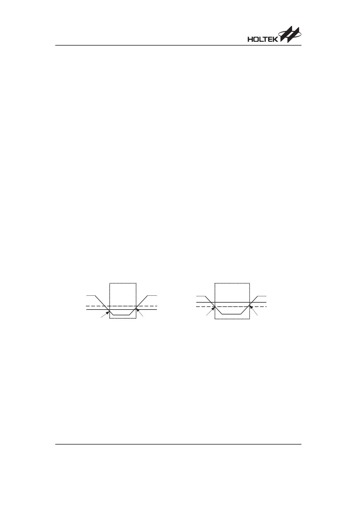
The power control situation is illustrated graphically below:
VDD
VCOMP
VBAT
Battery
Backup
Mode
2.55V
2.0V
VBAT-VBATHYS
VBAT+VBATHYS
Note: Battery switchover when VBAT < VCOMP
VDD
VBAT
VCOMP
Battery Backup
Mode
3.0V
2.55V
VCOMP
VCOMP+VCOMPHYS
Note: Battery switchover when VBAT > VCOMP
Low Power Mode
In normal mode, the HT1382 switched into battery backup mode when the VDD power is lost. This will
ensure that the device can accept a wide range of backup voltages from many types of sources while
reliably switching into backup mode. Another mode, called Low Power Mode, is available to allow
direct switching from VDD to VBAT without requiring VDD to drop below V . COMP The power switchover
circuit is disabled and less power is used while operating from VDD. Low Power Mode is activated via
the LPM bit.
Low Power Mode is useful when VDD is normally higher than V . BAT The device will switch from VDD to
VBAT when VDD drops below V , BAT with about 40mVof hysteresis to prevent any switchback of VDD after
switchover. In a system with VDD=5V and VBAT=3V, Low Power Mode can be used. However, it is not
recommended to use Low Power Mode in VDD=3.3V±10%, VBAT³3V.
Rev. 1.40
9
May 27, 2011
Share Link: 