HMP8115CN Просмотр технического описания (PDF) - Intersil
Номер в каталоге
Компоненты Описание
Список матч
HMP8115CN Datasheet PDF : 43 Pages
| |||
HMP8115
square or rectangular pixels are output. The output format is
4:2:2 for all modes except the RGB modes which use a 4:4:4
output format.
CLK2 INPUT
Note that the color subcarrier is derived from CLK2. Any jitter
on CLK2 will be transferred to the color subcarrier, resulting
in color changes. Thus, CLK2 should be derived from a sta-
ble clock source, such as a crystal. The use of a PLL to gen-
erate CLK2 is not recommended. CLK2 must have a 50ppm
accuracy and at least a 60/40% duty cycle to ensure proper
operation.
The CLK2 clock rate must be one of the following frequencies:
24.54MHz
27.00MHz
29.50MHz
The frequency of CLK2 must be 2x the desired output sam-
ple rate. The values in Table 1 below indicate the CLK2 clock
rate based on the video standard and pixel mode. The out-
put sample rate for the given video standard and pixel mode
is half the CLK2 clock rate.
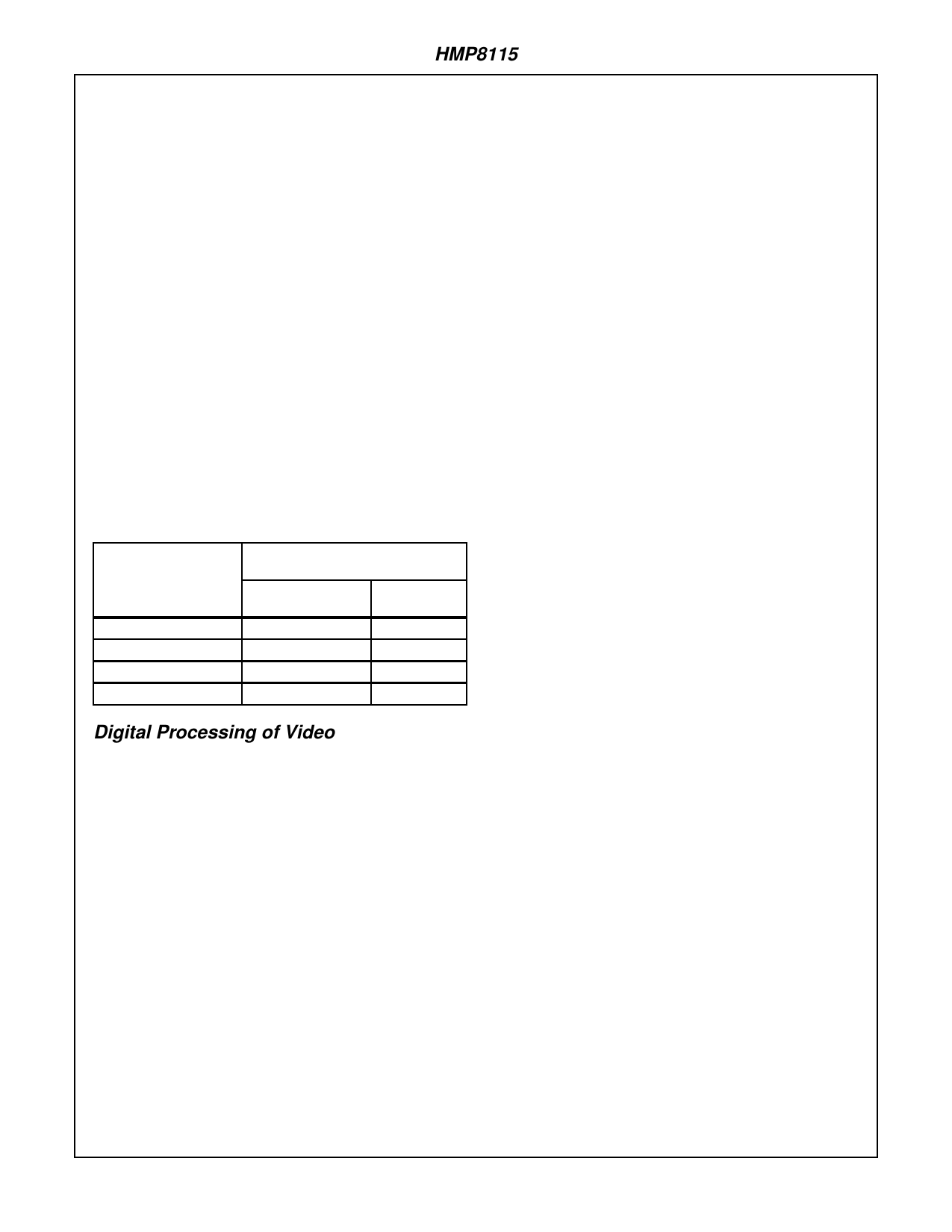
TABLE 1. VIDEO STANDARD CLOCK RATE SELECTION
SUMMARY
ALLOWABLE CLK2
FREQUENCIES (MHz)
VIDEO FORMAT
RECTANGULAR
PIXEL MODE
SQUARE
PIXEL MODE
(M) NTSC
27.00
24.54
(B, D, G, H, I, N) PAL
27.00
29.50
(M) PAL
27.00
24.54
(NC) PAL
27.00
29.50
Digital Processing of Video
Once the luma and chroma have been separated the
HMP8115 then performs programmable modifications (i.e.
contrast, coring, color space conversions, color AGC, etc.) to
the decoded video signal.
UV TO CbCr CONVERSION
The baseband U and V signals are scaled and offset to gen-
erate a nominal range of 16-240 for both the Cb and Cr data.
DIGITAL COLOR GAIN CONTROL
There are four types of color gain control modes available:
no gain control, automatic gain control, fixed gain control,
and freeze automatic gain control.
If “no gain control” is selected, the amplitude of the color dif-
ference signals (CbCr) is not modified, regardless of varia-
tions in the color burst amplitude. Thus, a gain of 1x is
always used for Cb and Cr.
If “automatic gain control” is selected, the amplitude of the
color difference signals (CbCr) is compensated for variations
in the color burst amplitude. The burst amplitude is averaged
with the two previous lines having a color burst to limit line-
to-line variations. A gain of 0.5x to 4x is used for Cb and Cr.
If “fixed gain control” is selected, the amplitude of the color
difference signals (CbCr) is multiplied by a constant, regard-
less of variations in the color burst amplitude. The constant
gain value is specified by the COLOR GAIN register 1CH. A
gain of 0.5x to 4x is used for Cb and Cr. Limiting the gain to
4x limits the amount of amplified noise.
If “freeze automatic gain control” is selected, the amplitude
of the color difference signals (CbCr) is multiplied by a con-
stant. This constant is the value the AGC circuitry generated
when the “freeze automatic gain” command was selected.
COLOR KILLER
If “enable color killer” is selected, the color output is turned
off when the running average of the color burst amplitude is
below approximately 25% of nominal for four consecutive
fields. When the running average of the color burst ampli-
tude is above approximately 25% of nominal for four consec-
utive fields, the color output is turned on. The color output is
also turned off when excessive phase error of the chroma
PLL is present.
If “force color off” is selected, color information is never
present on the outputs.
If “force color on” is selected, color information is present on
the outputs regardless of the color burst amplitude or
chroma PLL phase error.
Y PROCESSING
The black level is subtracted from the luminance data to
remove sync and any blanking pedestal information. Nega-
tive values of Y are supported at this point to allow proper
decoding of “below black” luminance levels.
Scaling is done to position black at 8-bit code 0 and white at
8-bit code 219.
A chroma trap filter may be used to remove any residual
color subcarrier from the luminance data. The center fre-
quency of the chroma trap is automatically determined from
the video standard being decoded. The chroma trap should
be disabled during S-video operation to maintain maximum
luminance bandwidth. Alternately, a 3MHz lowpass filter may
be used to remove high-frequency Y data. This may make a
noisy image more pleasing to the user, although softer.
Coring of the high-frequency Y data may be done to reduce
low-level high frequency noise.
Coring of the Y data may also be done to reduce low-level
noise around black. This forces Y data with the following val-
ues to a value of 0:
coring = 1: ± 1
coring = 2: ± 1, ± 2
coring = 3: ± 1, ± 2. ± 3
High-frequency components of the luminance signal may be
“peaked” to control the sharpness of the image. Maximum
gain may be selected to occur at either 2.6MHz or the color
7
Share Link: 