IRU1015 Просмотр технического описания (PDF) - International Rectifier
Номер в каталоге
Компоненты Описание
Список матч
IRU1015 Datasheet PDF : 8 Pages
| |||
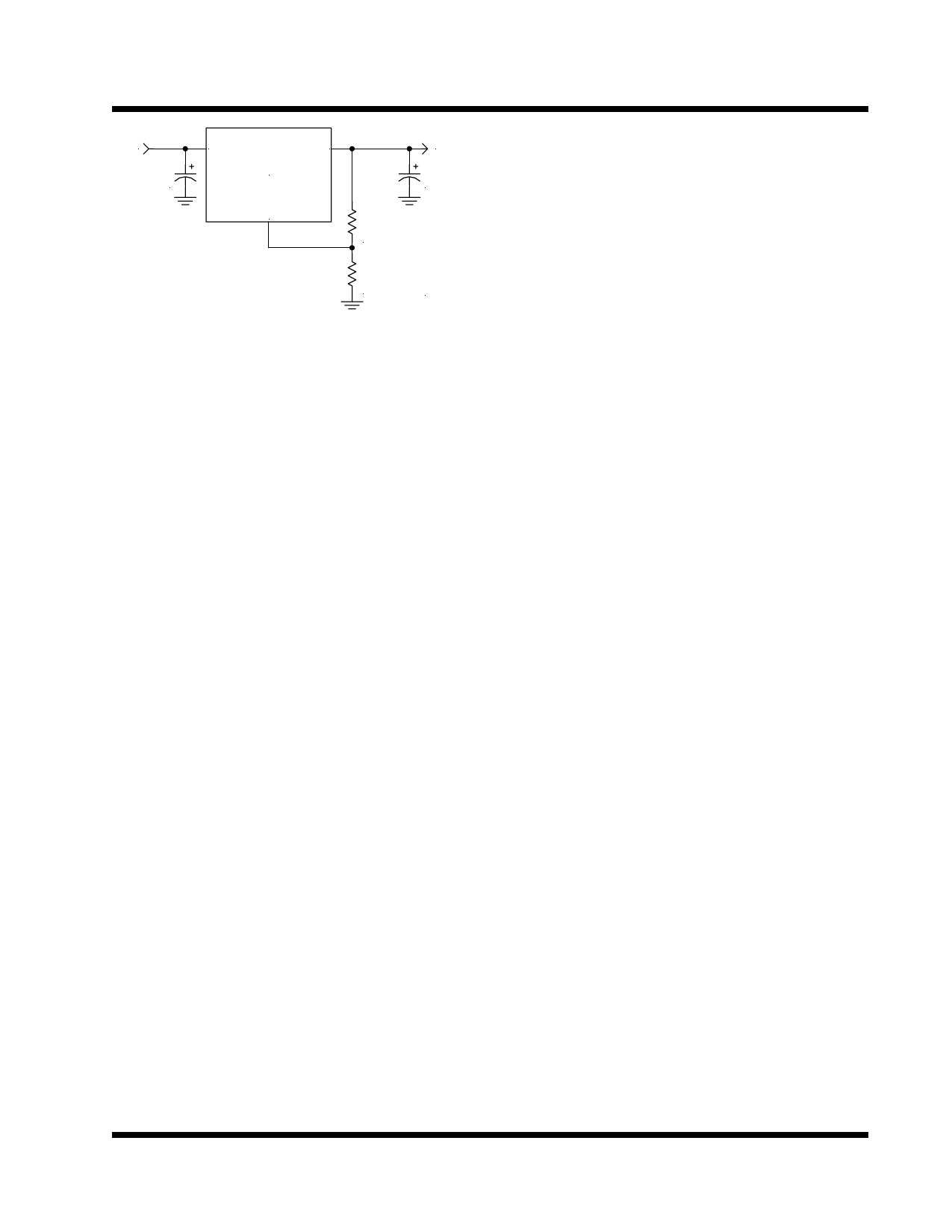
IRU1015
5V
C1
1500uF
Vin
Vout
IRU1015
Adj
3.45V
C2
1500uF
R1
121
1%
R2
215
1%
1015app4-1.1
Layout Consideration
The output capacitors must be located as close to the
Vout terminal of the device as possible. It is recom-
mended to use a section of a layer of the PC board as a
plane to connect the Vout pin to the output capacitors to
prevent any high frequency oscillation that may result
from excessive trace inductance.
Figure 6 - Final schematic for the regulator design
Rev. 1.1
06/29/01
7
Share Link: 