FSL126MRT Просмотр технического описания (PDF) - Fairchild Semiconductor
Номер в каталоге
Компоненты Описание
Список матч
FSL126MRT Datasheet PDF : 13 Pages
| |||
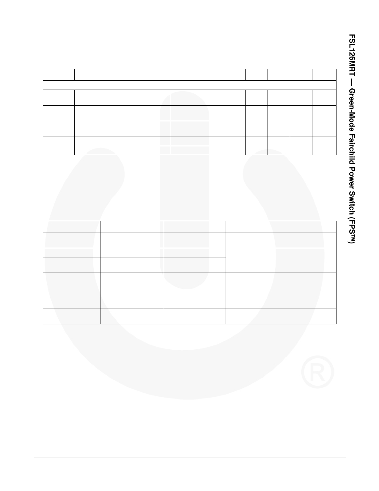
Electrical Characteristics (Continued)
TJ = 25°C unless otherwise specified.
Symbol
Parameter
Condition
Min.
Total Device Section
IOP
Operating Supply Current,
(Control Part in Burst Mode)
VCC=14V, VFB=0V
0.3
IOPS
Operating Switching Current,
(Control Part and SenseFET Part)
VCC=14V, VFB=2V
ISTART
ICH
VSTR
Start Current
Startup Charging Current
Minimum VSTR Supply Voltage
VCC=11V (Before VCC
Reaches VSTART)
85
VCC=VFB=0V, VSTR=40V
0.7
VCC=VFB=0V, VSTR Sweep
Notes:
12. Although these parameters are guaranteed, they are not 100% tested in production.
13. Average value.
14. tLEB includes gate turn-on time.
Typ. Max.
0.4
0.5
1.00 1.35
120 155
1.0
1.3
26
Unit
mA
mA
μA
mA
V
Comparison of KA5M0265R and FSL126MRT
Function
Random Frequency
Fluctuation
Operating Current
High-Voltage
Startup Circuit
KA5M0265RYDTU
N/A
7mA
N/A
Protections
OLP
OVP
TSD
Power Balance
Long tCLD
FSL126MRT
Advantages of FSL126MRT
Built-in
Low EMI
0.4mA
Built-in
Very low stand-by power
OLP
OVP
AOCP
TSD with Hysteresis
Very Short tCLD
Enhanced protections and high reliability
The difference of input power between the
low and high input voltage is quite small.
© 2012 Fairchild Semiconductor Corporation
FSL126MRT • Rev. 1.0.0
6
www.fairchildsemi.com
Share Link: 