ELM408 Просмотр технического описания (PDF) - Elm Electronics
Номер в каталоге
Компоненты Описание
Список матч
ELM408 Datasheet PDF : 10 Pages
| |||
ELM408
Output Waveforms
Once the ELM408 has some bounce-free signals
to work with, it can generate outputs based on them.
The output sequences that the ELM408 generates
depends on the direction of shaft rotation, and on the
level at the Write Enable input (pin 4). The direction
logic always assumes that the encoder is a standard
one, where the ‘A’ signal leads the ‘B’ for a clockwise
or ‘up’ rotation. Note that the level at pin 5 only
determines when the sequences are output, and does
not affect the waveshape or timing of them.
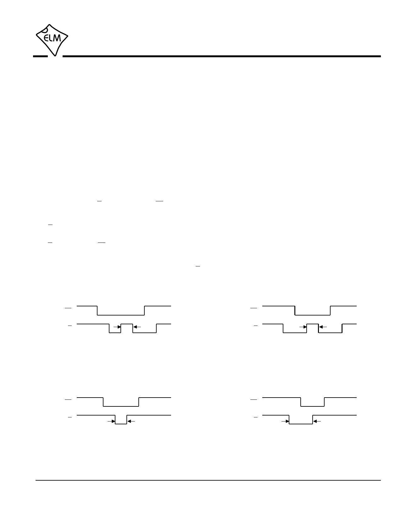
Figures 4 to 7 below show the sequences that the
ELM408 can generate. In all cases, the basic time
interval is 200 µsec (if it does not seem apparent).
Figures 4 and 5 show the two types of sequences that
would occur if the Write Enable is low (ie disabled).
The level at the U/D output when the CS signal goes
low determines whether the the controlled device will
count up (level is high), or down (level is low) when the
U/D pin next goes from low to high.
For many digital potentiometers, the level at the
U/D pin when the CS output returns high determines
whether the current setting of the digital potentiometer
is to be stored in non-volatile memory or not. If the
ELM408’s Write Enable input is high, then the U/D
output will be held high during the transition, causing a
write for many digital potentiometers. The resulting
waveforms are shown in Figures 6 and 7.
The logic to decode the motion of an encoder
shaft, and so decide when to provide output
sequences is not as simple as it would first appear.
Some authorities recommend simply monitoring an
input and when it changes, provide an output based on
the level of the other input. This does not always work,
as the encoder can output multiple signals from only
the ‘A’ or or only the ‘B’ contact if the shaft is moved
ever so slightly when at the detent or at the mid-point
position (between detents). Simply seeing one input
change is not sufficient to say that there is any
significant shaft rotation.
The ELM408 monitors both ‘A’ and ‘B’ transitions,
and determines the outputs based on the sequence in
which the transitions have occurred. This is a better
way to guarantee that the output signals are generated
properly. The internal logic also performs some self-
checking, and monitors for problems such as an output
pulse being initiated before the previous one had
completed, which might occur for some very fast
inputs (the second one will be ignored in this case).
The output of the ELM408 is a series of pulses, as
shown in Figures 8 and 9. The first figure shows 2x
CS
200
U/D
µsec
Figure 4. Up (Clockwise) with
Write Enable = Low
CS
200
U/D
µsec
Figure 5. Down (Counterclockwise) with
Write Enable = Low
CS
U/D
200
µsec
Figure 6. Up (Clockwise) with
Write Enable = High
CS
U/D
400
µsec
Figure 7. Down (Counterclockwise) with
Write Enable = High
ELM408DSA
Elm Electronics – Circuits for the Hobbyist
www.elmelectronics.com
7 of 10
Share Link: 