ELM307 Просмотр технического описания (PDF) - Elm Electronics
Номер в каталоге
Компоненты Описание
Список матч
ELM307 Datasheet PDF : 4 Pages
| |||
ELM307
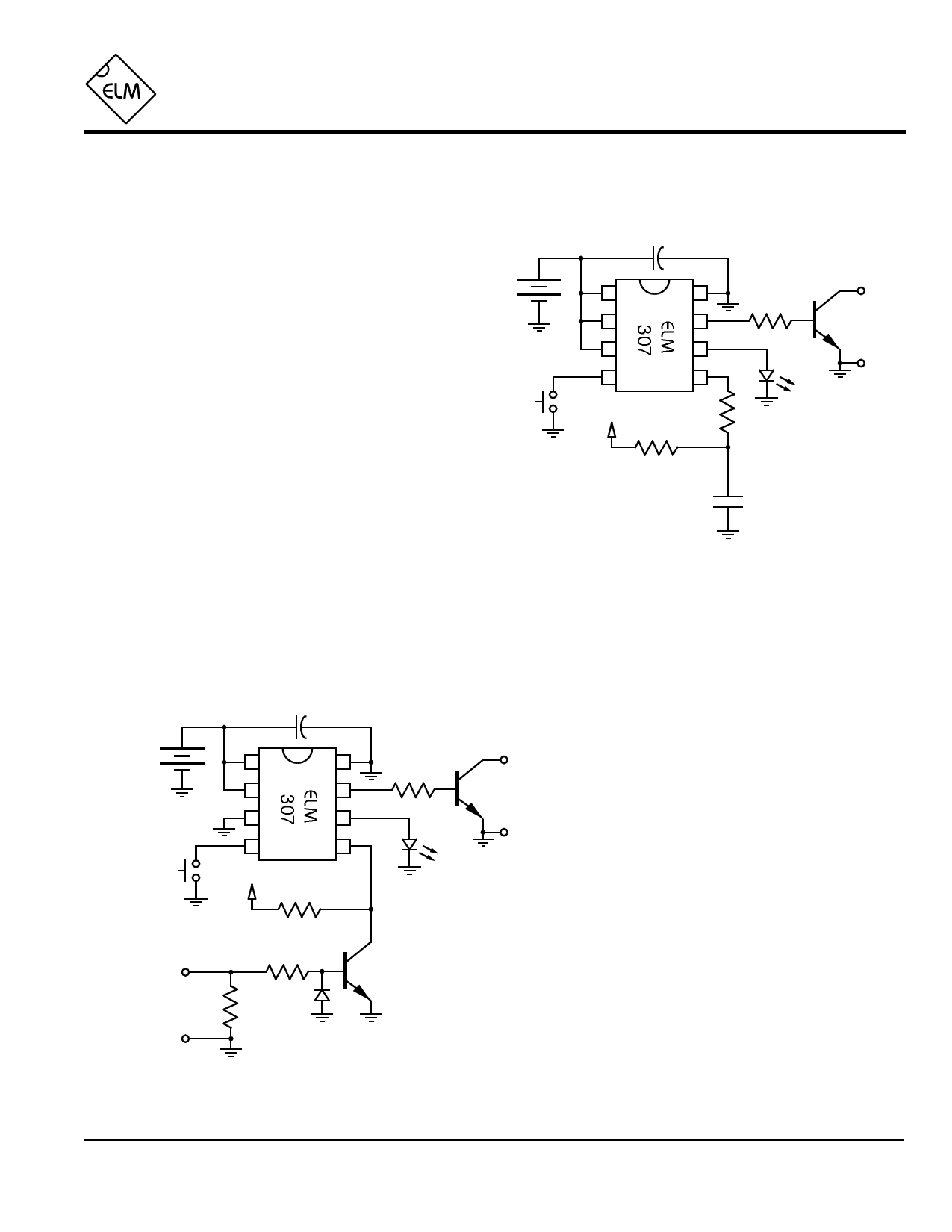
Example Applications
Figures 1 and 2 show two typical circuits that the
ELM307 can be used in. The first is labelled ‘Party
Camera’ but really applies to any candid situation
where a switch is used to initiate the picture being
taken.
Although both circuits show a 3V battery for a
supply, this is only for portability. Any convenient
supply that is between 3V and 5.5V could just as
easily be used. Note that both supplies are bypassed
with 0.1µF capacitors. This is good practice, but could
be eliminated if cost is a concern, and the battery is
electrically close to the ELM307.
In Figure 1, PW and Delay are both at a high
level, so the circuit is configured for a 1 second ouput
with a minimum delay of 5 seconds between outputs.
An NPN transistor (2N3904 or similar) provides the
interface to the camera. Fortunately most cameras
these days (including disposables) use a momentary
contact for the shutter control, and this transistor can
simply be connected across that button to initiate a
picture. You may have to experiment a little to get the
polarity correct, though. An additional 33KΩ resistor is
shown connected in series with pin 5 to provide some
protection from electrostatic discharges. This is a
good idea if the initiating contact is located more than
a few feet from the ELM307. Note that there is no
3V +
power
0.1µF
1
8
2
7
3
6
4
5
+3V
33KΩ
33KΩ
AM radio
headphone
output
2.2KΩ
15Ω
Figure 2. Lightning Detector
3V +
power
1
2
3
4
+3V
0.1µF
8
7
6
5
33KΩ
(see text)
33KΩ
33KΩ
Figure 1. Party Camera
initiating
contact
Camera
shutter
control
resistor required in series with the LED in this circuit,
as internal circuitry limits the current to a safe value. If
a higher supply level is used, a small value resistor
(220Ω) should be connected in series with the LED.
The circuit shown in Figure 2 can be used to
capture photos of lightning (as long as the camera’s
inherent delay in responding is not so great that the
flash has dissipated). Some cameras have a
considerable delay in opening the shutter after
Camera
shutter
control
the button is pressed, and may not be
acceptable for this use.
The circuit shown is virtually identical to that
of figure 1, except that an additional NPN
transistor has been connected to amplify the
output of an AM radio and trigger the circuit.
In operation, the ELM307 is placed in the test
mode, the AM radio is tuned between stations, and its
volume is adjusted to trigger the LED only on lightning
flashes. When ready, the pushbutton is held for 3
seconds then released, switching the circuit to the run
mode. Hopefully the camera is pointing in the right
direction when a flash is detected.
Many variations on these circuits can be used to
trigger a camera, only limited by your imagination.
Why not connect an ELM460 for a 200sec period,
feed it into the ELM307 trigger, then put everything on
a kite and go fly it…
ELM307DSA
Elm Electronics – Circuits for the Hobbyist
< http://www.elmelectronics.com/ >
4 of 4
Share Link: 