AQV112KLAZ Просмотр технического описания (PDF) - Matsushita Electric Works
Номер в каталоге
Компоненты Описание
Список матч
AQV112KLAZ Datasheet PDF : 6 Pages
| |||
AQY2/AQV1
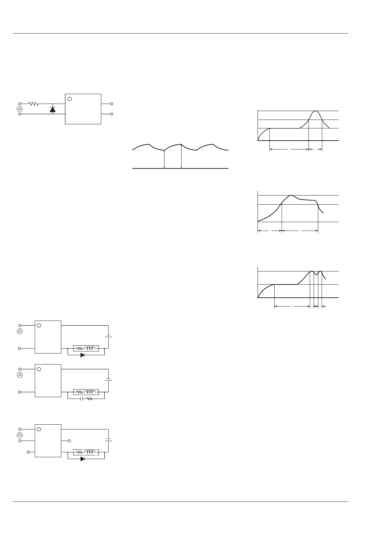
CAUTIONS FOR USE
1. Surge voltages at the input
If reverse surge voltages are present at
the input terminals, connect a diode in
reverse parallel across the input terminals
and keep the reverse voltages below the
reverse breakdown voltage.
1
4
2
3
2. Unused terminals
The No. 3 and 5 terminal is used with the
circuit inside the relay. Therefore, do not
connect it to the external circuitry with
either connection method A, B or C. (Non-
latch type)
3. It is possible that in-rush current will
be detected as short current, and
oscillation will be initiated. Please
confirm before use.
4. Please avoid exposing the unit to
short status for longer than 24 hours.
Long periods of exposure to short
status could damage the internal IC
(non-latch type only).
5. Short across terminals
Do not short circuit between terminals
when relay is energized. There is
possibility of breaking the internal IC.
6. Output spike voltages
1) If an inductive load generates spike
voltages which exceed the absolute
maximum rating, the spike voltage must
be limited. Typical circuits are shown
below.
Latch type
1
4
Load
2
3
Add a clamp diode
to the load
1
4
Load
2
3
Add a CR snubber
circuit to the load
Non-latch type
1
6
2
5
Load
3
4
Add a clamp diode
to the load
2) If spike voltages generated at the load
are limited with a clamp diode and the
circuit wires are long, spike voltages will
occur by inductance. Keep wires as short
as possible to minimize inductance.
7. Ripple in the input power supply
If ripple is present in the input power
supply, observe the following:
2) Keep the LED operate current at Emin,
maintain min. 5 mA (Latch type), 10 mA
(Non-latch type).
1) For LED operate current 50 mA or less
at Emax.
Emin.
Emax.
8. When soldering terminals, keep
soldering time to within 10 s at 260°C
500°F.
9. Cleaning solvents compatibility
The PhotoMOS relay forms an optical
path by coupling a light-emitting diode
(LED) and photodiode via transparent
silicon resin. For this reason, unlike other
directory element molded resin products
(e.g., MOS transistors and bipolar
transistors), avoid ultrasonic cleansing if
at all possible. We recommend cleaning
with an organic solvent. If you cannot
avoid using ultrasonic cleansing, please
ensure that the following conditions are
met, and check beforehand for defects.
• Frequency: 27 to 29 kHz
• Ultrasonic output:
No greater than 0.25W/cm2
• Cleaning time:
No longer than 30 s
• Cleanser used: Asahiklin AK-225
• Other:
Submerge in solvent in order to prevent
the PCB and elements from being
contacted directly by the ultrasonic
vibrations.
Note: Applies to unit area ultrasonic output for
ultrasonic baths.
10. Transportation and storage
1) Extreme vibration during transport will
warp the lead or damage the relay.
Handle the outer and inner boxes with
care.
2) Storage under extreme conditions will
cause soldering degradation, external
appearance defects, and deterioration of
the characteristics. The following storage
conditions are recommended:
• Temperature: 0 to 45°C 32 to 113°F
• Humidity: Less than 70% R.H.
• Atomosphere: No harmful gasses such
as sulfurous acid gas, minimal dust.
11. Soldering
1) When soldering PC board terminals,
keep soldering time to within 10 s at
260°C 500°F .
2) When soldering surface-mount
terminals, the following conditions are
recommended.
(1) IR (Infrared reflow) soldering method
T3
T2
T1
t1
t2
T1 = 155 to 165°C 311 to 329°F
T2 = 180°C 200°C 356 to 392°F
T3 = 245°C 473°F or less
t1 = 120 s or less
t2 = 30 s or less
(2) Vapor phase soldering method
T2
T1
t1
t2
T1 = 180 to 200°C 366 to 392°F
T2 = 215°C 419°F or less
t1 = 40 s
t2 = 90 s or less
(3) Double wave soldering method
T2
T1
t1
t2 t3
T1 = 155 to 165°C 311 to 329°F
T2 = 260°C 500°F or less
t1 = 60 s or less
t2+t3 = 5 s or less
(4) Soldering iron method
Tip temperature: 280 to 300°C 536 to
572°F
Wattage: 30 to 60 W
Soldering time: within 5 s
(5) Others
Check mounting conditions before using
other soldering methods (hot-air, hot
plate, pulse heater, etc.)
• The temperature profile indicates the
temperature of the soldered terminal on
the surface of the PC board. The ambient
temperature may increase excessively.
Check the temperature under mounting
conditions.
• The conditions for the infrared reflow
soldering apply when preheating using
the VPS method.
12
Share Link: 