L78S15T Просмотр технического описания (PDF) - STMicroelectronics
Номер в каталоге
Компоненты Описание
Список матч
L78S15T Datasheet PDF : 21 Pages
| |||
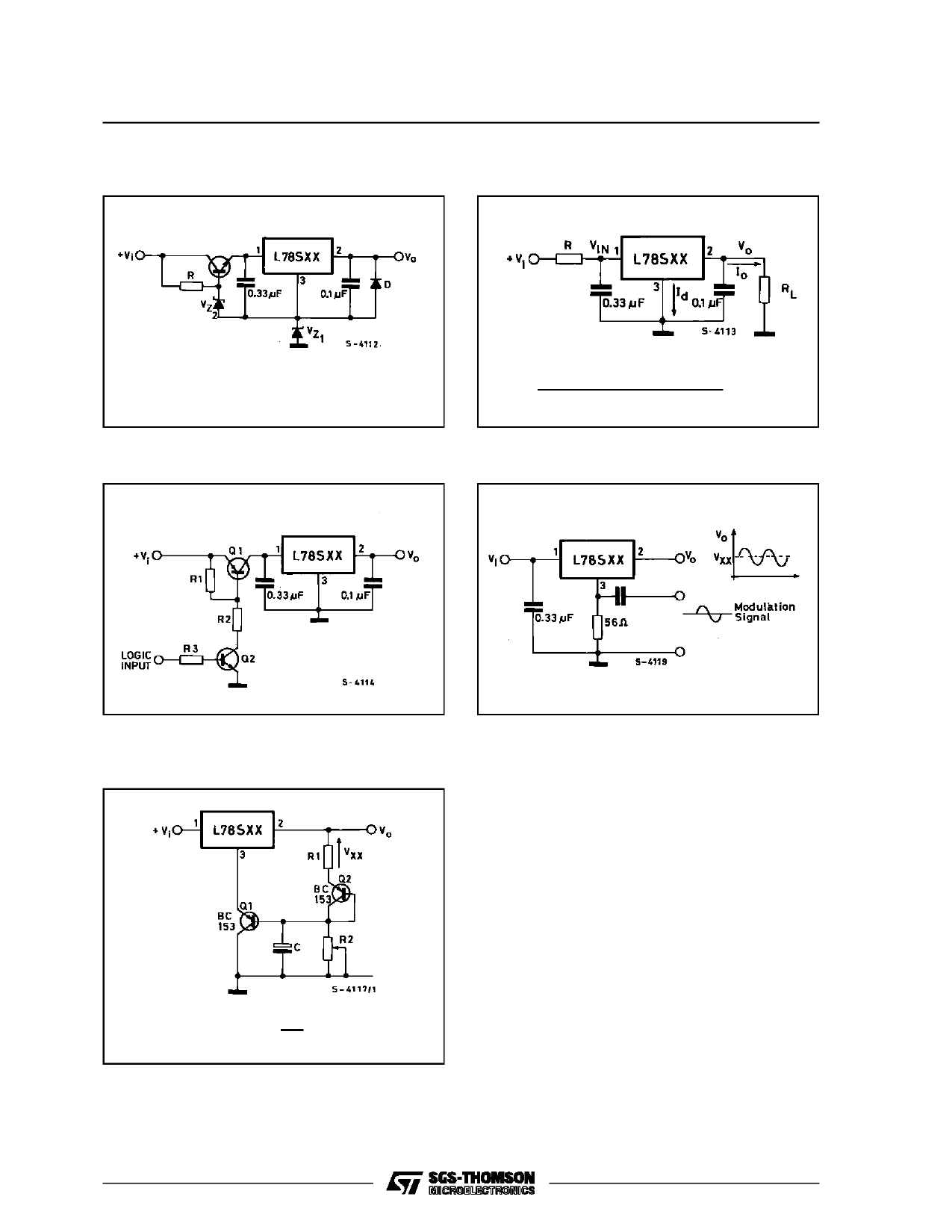
Figure 27 : High Input and Output Voltage.
L78S00 SERIES
Figure 28 : Reducing Power Dissipation with
Dropping Resistor.
VO = VXX + VZ1
Figure 29 : Remote Shuntdown.
R = Vi(min) – VXX – VDROP(max)
IO(max) + Id(max)
Figure 30 : Power AM Modulator (unity voltage
gain, Io ≤ 1A).
Figure 31 : Adjustable Output Voltage with Tem-
perature Compensation.
Note : The circuit performs well up to 100KHz.
VO = VXX (1 +
R2
R1
) + VBE
Note :Q2 is connected as a diode in order to compensat e
the vari ati on of the Q1 VBE wi th the temper atur e. C
allows a slow rise-time of the VO
17/21
Share Link: 