ADM3483 Просмотр технического описания (PDF) - Analog Devices
Номер в каталоге
Компоненты Описание
Список матч
ADM3483 Datasheet PDF : 20 Pages
| |||
Data Sheet
3.3 V Slew Rate Limited, Half- and
Full-Duplex, RS-485/RS-422 Transceivers
ADM3483/ADM3485/ADM3488/ADM3490/ADM3491
FEATURES
Operate with 3.3 V supply
Interoperable with 5 V logic
EIA RS-422 and RS-485 compliant over full
common-mode range
Data rate options
ADM3483/ADM3488: 250 kbps
ADM3485/ADM3490/ADM3491: 10 Mbps
Half- and full-duplex options
Reduced slew rates for low EMI (ADM3483 and ADM3488)
2 nA supply current in shutdown mode
(ADM3483/ADM3485/ADM3491)
Up to 32 transceivers on the bus
−7 V to +12 V bus common-mode range
Specified over the –40°C to +85°C temperature range
8 ns skew (ADM3485/ADM3490/ADM3491)
8-lead SOIC and 14-lead SOIC (ADM3491 only) packages
APPLICATIONS
Low power RS-485/RS-422 applications
Telecom
Industrial process control
HVAC
GENERAL DESCRIPTION
The ADM3483/ADM3485/ADM3488/ADM3490/ADM3491 are
low power, differential line transceivers designed to operate using a
single 3.3 V power supply. Low power consumption, coupled with a
shutdown mode, makes the ADM3483/ADM3485/ADM3488/
ADM3490/ADM3491 ideal for power-sensitive applications.
The ADM3488/ADM3490/ADM3491 feature full-duplex com-
munication, while the ADM3483/ADM3485 are designed for
half-duplex communication.
The ADM3483/ADM3488 feature slew rate limited drivers that
minimize EMI and reduce reflections caused by improperly ter-
minated cables, allowing error-free data transmission at data rates
up to 250 kbps.
The ADM3485/ADM3490/ADM3491 transmit at up to 10 Mbps.
The receiver input impedance is 12 kΩ, allowing up to 32 trans-
ceivers to be connected on the bus. A thermal shutdown circuit
prevents excessive power dissipation caused by bus contention or
by output shorting. If a significant temperature increase is detected
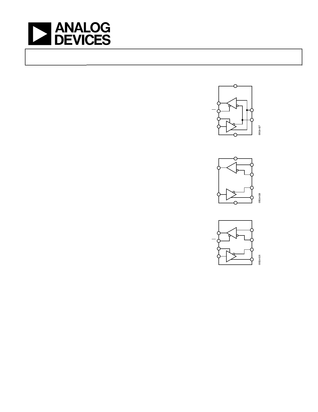
FUNCTIONAL BLOCK DIAGRAMS
VCC
ADM3483/
ADM3485
RO
R
RE
A
DE
B
DI
D
GND
Figure 1.
VCC
A
RO
R
B
ADM3488/
ADM3490
Z
DI
D
Y
GND
Figure 2.
ADM3491
A
RO
R
RE
B
DE
Z
DI
D
Y
Figure 3.
in the internal driver circuitry during fault conditions, then the
thermal shutdown circuit forces the driver output into a high
impedance state. If the inputs are unconnected (floating), the
receiver contains a fail-safe feature that results in a logic high
output state. The parts are fully specified over the commercial
and industrial temperature ranges. The ADM3483/ADM3485/
ADM3488/ADM3490 are available in 8-lead SOIC_N; the
ADM3491 is available in a 14-lead SOIC_N.
Rev. E
Information furnished by Analog Devices is believed to be accurate and reliable. However, no
responsibility is assumed by Analog Devices for its use, nor for any infringements of patents or other
rights of third parties that may result from its use. Specifications subject to change without notice. No
license is granted by implication or otherwise under any patent or patent rights of Analog Devices.
Trademarks and registered trademarks are the property of their respective owners.
One Technology Way, P.O. Box 9106, Norwood, MA 02062-9106, U.S.A.
Tel: 781.329.4700
www.analog.com
Fax: 781.461.3113 ©2005-2011 Analog Devices, Inc. All rights reserved.
Share Link: 