ADL5374ACPZ-WP Просмотр технического описания (PDF) - Analog Devices
Номер в каталоге
Компоненты Описание
Список матч
ADL5374ACPZ-WP Datasheet PDF : 20 Pages
| |||
THEORY OF OPERATION
CIRCUIT DESCRIPTION
Overview
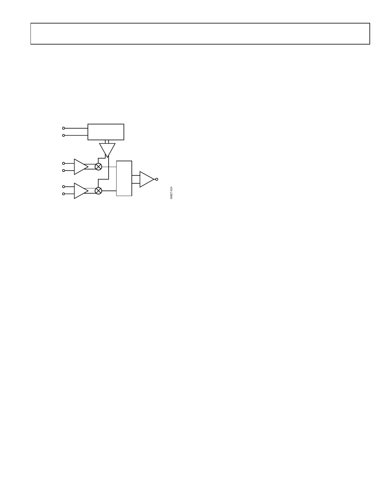
The ADL5374 can be divided into five circuit blocks: the LO
interface, the baseband voltage-to-current (V-to-I) converter,
the mixers, the differential-to-single-ended (D-to-S) stage, and
the bias circuit. A detailed block diagram of the device is shown
in Figure 24.
LOIP
LOIN
PHASE
SPLITTER
IBBP
IBBN
QBBP
QBBN
Σ
OUT
Figure 24. Block Diagram
The LO interface generates two LO signals in quadrature. These
signals are used to drive the mixers. The I and Q baseband input
signals are converted to currents by the V-to-I stages, which
then drive the two mixers. The outputs of these mixers combine
to feed the output balun, which provides a single-ended output.
The bias cell generates reference currents for the V-to-I stage.
LO Interface
The LO interface consists of a polyphase quadrature splitter
followed by a limiting amplifier. The LO input impedance is set
by the polyphase. For optimal performance, the LO should be
driven differentially. Each quadrature LO signal then passes
through a limiting amplifier that provides the mixer with a
limited drive signal.
ADL5374
V-to-I Converter
The differential baseband inputs (QBBP, QBBN, IBBN, and
IBBP) consist of the bases of PNP transistors, which present a
high impedance. The voltages applied to these pins drive the
V-to-I stage that converts baseband voltages into currents. The
differential output currents of the V-to-I stages feed each of their
respective Gilbert-cell mixers. The dc common-mode voltage at
the baseband inputs sets the currents in the two mixer cores.
Varying the baseband common-mode voltage influences the
current in the mixer and affects overall modulator performance.
The recommended dc voltage for the baseband common-mode
voltage is 500 mV dc.
Mixers
The ADL5374 has two double-balanced mixers: one for the
in-phase channel (I-channel) and one for the quadrature
channel (Q-channel). Both mixers are based on the Gilbert cell
design of four crossconnected transistors. The output currents
from the two mixers sum together into a load. The signal
developed across this load is used to drive the D-to-S stage.
D-to-S Stage
The output D-to-S stage consists of an on-chip balun that
converts the differential signal to a single-ended signal. The
balun presents high impedance to the output (VOUT). Therefore,
a matching network may be needed at the output for optimal
power transfer.
Bias Circuit
An on-chip band gap reference circuit is used to generate a
proportional-to-absolute temperature (PTAT) reference current
for the V-to-I stage.
Rev. 0 | Page 11 of 20
Share Link: 