AD9803 Просмотр технического описания (PDF) - Analog Devices
Номер в каталоге
Компоненты Описание
Список матч
AD9803 Datasheet PDF : 19 Pages
| |||
THEORY OF OPERATION
Introduction
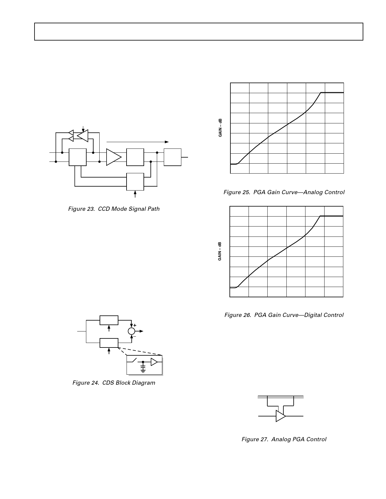
The AD9803 is a 10-bit analog-to-digital interface for CCD
cameras. The block level diagram of the system is shown in
Figure 23. The device includes a correlated double sampler
(CDS), 0 dB–30 dB programmable gain amplifier (PGA), black
level correction loop, input clamp and voltage reference. The
only external analog circuitry required at the system level is an
emitter follower buffer between the CCD output and AD9803
inputs.
CLPDM
INPUT CLAMP
DIFFERENTIAL SIGNAL PATH
PIN
CDS
PGA
SHA
DIN
ADC
INTEG
BLACK LEVEL CLAMP
CLPOB
Figure 23. CCD Mode Signal Path
Correlated Double Sampling (CDS)
CDS is important in high performance CCD systems as a
method for removing several types of noise. Basically, two
samples of the CCD output are taken: one with the signal
present (“data”) and one without (“reference”). Subtracting
these two samples removes any noise which is common—or
correlated—to both.
Figure 24 shows the block diagram of the AD9803’s CDS. The
S/H blocks are directly driven by the input and the sampling
function is performed passively, without the use of amplifiers.
This implementation relies on the off-chip emitter follower
buffer to drive the two 10 pF sampling capacitors. Only one
capacitor at a time is seen at the input pin.
FROM
CCD
S/H
S
OUT
Q1
S/H
Q2
10pF
Figure 24. CDS Block Diagram
The AD9803 actually uses two CDS circuits in a “ping pong”
fashion to allow the system more acquisition time. In this way,
the output from one of the two CDS blocks will be valid for an
entire clock cycle. Thus, the bandwidth requirement of the
subsequent gain stage is reduced as compared to that for a single-
channel CDS system. This lower bandwidth translates to lower
power and noise.
AD9803
Programmable Gain Amplifier (PGA)
The on-chip PGA provides a gain range of 0 dB–30 dB, which
is “linear in dB.” Typical gain characteristics are shown in
Figures 25 and 26.
40
35
30
25
20
15
10
5
0
–5
0
0.5
1.0
1.5
2.0
2.5
3.0
PGACONT1 – Volts
Figure 25. PGA Gain Curve—Analog Control
40
35
30
25
20
15
10
5
0
–5
0
171
341
511
682
852
1023
PGA GAIN REGISTER
Figure 26. PGA Gain Curve—Digital Control
As shown in Figure 27, analog PGA control is provided through
the PGACONT1 and PGACONT2 inputs. PGACONT1 pro-
vides coarse and PGACONT2 fine (1/16) gain control. The
PGA gain can also be controlled using the internal 10-bit DAC
through the serial digital interface. The gain characteristic
shown in Figure 26, with the internal DAC providing the same
control range as PGACONT1. See the Serial Interface Specifi-
cations for more details.
PGACONT1 PGACONT2
A
PGACONT1 = COARSE CONTROL
PGACONT2 = FINE (1/16) CONTROL
Figure 27. Analog PGA Control
REV. 0
–11–
Share Link: 