LTC1093C Просмотр технического описания (PDF) - Linear Technology
Номер в каталоге
Компоненты Описание
Список матч
LTC1093C Datasheet PDF : 32 Pages
| |||
LTC1091/LTC1092
LTC1093/LTC1094
APPLICATI S I FOR ATIO
MSB-First/LSB-First (MSBF)
Unipolar Output Code (UNI = 1)
The output data of the LTC1091/LTC1093/LTC1094 is
programmed for MSB-first or LSB-first sequence using
the MSBF bit. When the MSBF bit is a logical one, data will
appear on the DOUT line in MSB-first format. Logical zeros
will be filled in indefinitely following the last data bit to
accommodate longer word lengths required by some
OUTPUT CODE
1111111111
1111111110
•
•
•
0000000001
0000000000
INPUT VOLTAGE
VREF – 1LSB
VREF – 2LSB
•
•
•
1LSB
0V
INPUT VOLTAGE
(VREF = 5V)
4.9951V
4.9902V
•
•
•
0.0049V
0V
microprocessors. When the MSBF bit is a logical zero,
1091-4AI13
LSB-first data will follow the normal MSB-first data on the
DOUT line. (See operating sequence).
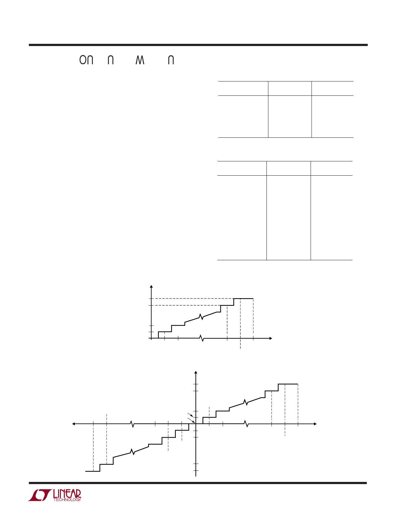
Unipolar/Bipolar (UNI)
The UNI bit of the LTC1093/LTC1094 determines whether
the conversion will be unipolar or bipolar. When UNI is a
logical one, a unipolar conversion will be performed on the
selected input voltage. When UNI is a logical zero, a bipolar
conversion will result. The input span and code assign-
ment for each conversion type are shown in the figures
below.
The LTC1091/LTC1092 are permanently configured for
unipolar mode.
Bipolar Output Code (UNI = 0) LTC1093/LTC1094 Only
OUTPUT CODE
0111111111
0111111110
•
•
•
0000000001
0000000000
1111111111
1111111110
•
•
•
1000000001
1000000000
INPUT VOLTAGE
VREF – 1LSB
VREF – 2LSB
•
•
•
1LSB
0V
–1LSB
–2LSB
•
•
•
–(VREF) + 1LSB
–(VREF)
INPUT VOLTAGE
(VREF = 5V)
4.9902V
4.9805V
•
•
•
0.0098V
0V
–0.0098V
–0.0195V
•
•
•
–4.9902V
–5.000V
1091-4AI14
Unipolar Transfer Curve (UNI = 1)
1111111111
1111111110
0000000001
0000000000
0V
1LSB
VREF – 2LSB
VREF
VREF – 1LSB
VIN
1091-4 AI11
Bipolar Transfer Curve (UNI = 0) LTC1093/LTC1094 Only
–VREF + 1LSB
–VREF
0111111111
0111111110
0000000001
0000000000
–1LSB
–2LSB
1LSB
1111111111
1111111110
1000000001
1000000000
VREF – 2LSB
VREF
VREF – 1LSB
VIN
1091-4 AI12
15
Share Link: 