31002A Просмотр технического описания (PDF) - Unisonic Technologies
Номер в каталоге
Компоненты Описание
Список матч
31002A Datasheet PDF : 6 Pages
| |||
31002A
LINEAR INTEGRATED CIRCUIT
APPLICATION NOTE
The application circuit illustrates the use of the UTC 31002A device in typical telephone tone ringer application.
The AC ringer signal voltage appears across the TIP and RING inputs of the circuit and is attenua-ted by capacitor
C1 and resistor R1.
C1 also provides isolation from DC voltage (48V) on the exchanged line.
After full wave rectification by the bridge diode, the wave form is filtered by capacitor C4 to provide a DC supply for
the tone ringer chip.
As this voltage exceeds the initiation voltage (Vsi), oscillation starts.
With the components shown, the output frequency chops between 512Hz (FH1) and 640 Hz (FH2) at a 10 Hz (FL)
rate.
The loudspeaker load is coupled through a 1300Ω to 8Ω transformer.
The output coupling capacitor C5 is required with transformer coupled loads.
When driving a pizeo-ceramic transducer type load, the coupling C5 and transformer (1300Ω:8Ω) are not required.
However, a current limiting resistor is required.
The low frequency oscillator oscillates at a rate (FL) controlled by an external resistor (R2) and capacitor (C2).
The frequency can be determined using the relation FL=1/1.289 R2* C2. The high frequency oscillates at a FH1,
FH2 controlled by an external resistor (R3) and capacitor (C3). The frequency can be determined using the relation
FH1=1/1.504 R3*C3 and FH2=1/1.203 R3*C3
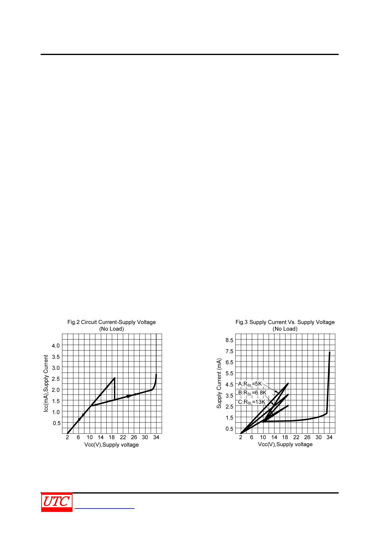
Pin 2 of the UTC 31002A allows connection of external resistor RSL, which is used to program the slope of the
supply current vs. supply voltage characteristics (see Fig.3), and hence the supply current up to the initiation voltage
(Vsi). This initiation voltage remains constant independent of RSL.
The supply current drawn prior to triggering varies inversely with RSL, decreasing for increasing value of
resistance. Thus, increasing the value of RSL, will decrease the amount of AC ringing current required to trigger the
device. As such, longer sucribser loops are possible since less voltage is dropped per unit length of loop wire due to
the lower current level. RSL can also be used to compensated for smaller AC coupling capacitors (C5 on Fig.4)
(higher impedance) to the line which can be used to alter the ringer equivalence number of a tone ringer circuit.
The graph in Fig.3 illustrates the variation of supply current with supply voltage of the UTC 31002A.
Three curves are drawn to show the variation of initiation current with RSL. Curve B ( RSL=6.8K) shows the I-V
characteristic for UTC 31002A tone ringer. Curve A is a plot with RSL<6.8KΩ and shows an increase in the current
drawn up to the initiation voltage Vsi. The I-V characteristic after initiation remains unchanged. Curve C illustrates
the effect of increasing RSL above 6.8K initiation current decreases but again current alter triggering is unchanged.
UNISONIC TECHNOLOGIES CO., LTD
www.unisonic.com.tw
5 of 6
QW-R108-005.C
Share Link: 