CS453GTVA5 Просмотр технического описания (PDF) - Cherry semiconductor
Номер в каталоге
Компоненты Описание
Список матч
CS453GTVA5 Datasheet PDF : 5 Pages
| |||
Circuit Description
Inductive actuators such as automotive electronic fuel
injectors, relays, solenoids and hammer drivers can be
powered more efficiently by providing a high current
drive until actuation (pull-in) occurs and then decreasing
the drive current to a level which will sustain actuation.
Pull-in and especially dropout times of the actuators are
also improved.
The fundamental output characteristic of the CS452/453
provides a low impedance saturated power switch until
the load current reaches a predetermined high-current
level and then changes to a current source of lower magni-
tude until the device is turned off. This output characteris-
tic allows the inductive load to control its actuation time
during turn-on while minimizing power and stored energy
during the sustain period, thereby promoting a fast turn-
off time.
Automotive injectors at present time come in two types.
The large throttle body injectors have an inductance of
about 2.0mH and an impedance of 1.2½ and require the
CS453 driver. The smaller type, popular worldwide, have
an inductance of 4.0mH and an impedance of 2.4½ and
needs about a 2.0A pulse for good results, which can be
met with the CS452. Some designs are planned which
employ two of the smaller types in parallel. The induc-
tance of the injectors are much larger at low current,
decreasing due to armature movement and core saturation
to the values above at rated current.
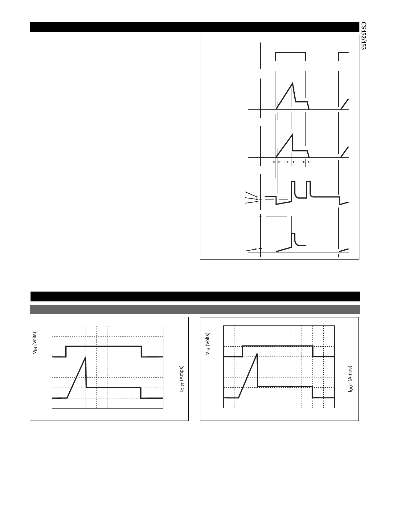
Input Signal
VIN
>1.4V
0
Load
Current
Ipk
2.0
4.0ms
Output
Current
Ipk
Ipk (SENSE)
Isus
ti
Output
Voltage
VZ
VBAT
VBAT - (Isus RL)
VSAT
VZ Ipk
Power
Dissipation VZ Isus
tp
td
Operating frequencies range from 5.0Hz to 250Hz depend-
ing on the injector location and engine type. Duty cycle in
some designs reaches 80%.
(VBAT - Isus RL) Isus
VSAT Ipk
Figure 1. Operating Waveforms (Max. Frequency 250Hz, CONTROL
Grounded)
Timing Diagrams
Input Voltage and Output Current vs. Time
CS452
CS453
10
10
5
5
0
2.4
0
4
1.8
3
1.2
2
0.6
1
IOUT
0
IOUT
0
0 1 2 3 4 5 6 7 8 9 10
0 1 2 3 4 5 6 7 8 9 10
3
Share Link: 