MAX127ACAI(2012) Просмотр технического описания (PDF) - Maxim Integrated
Номер в каталоге
Компоненты Описание
Список матч
MAX127ACAI Datasheet PDF : 16 Pages
| |||
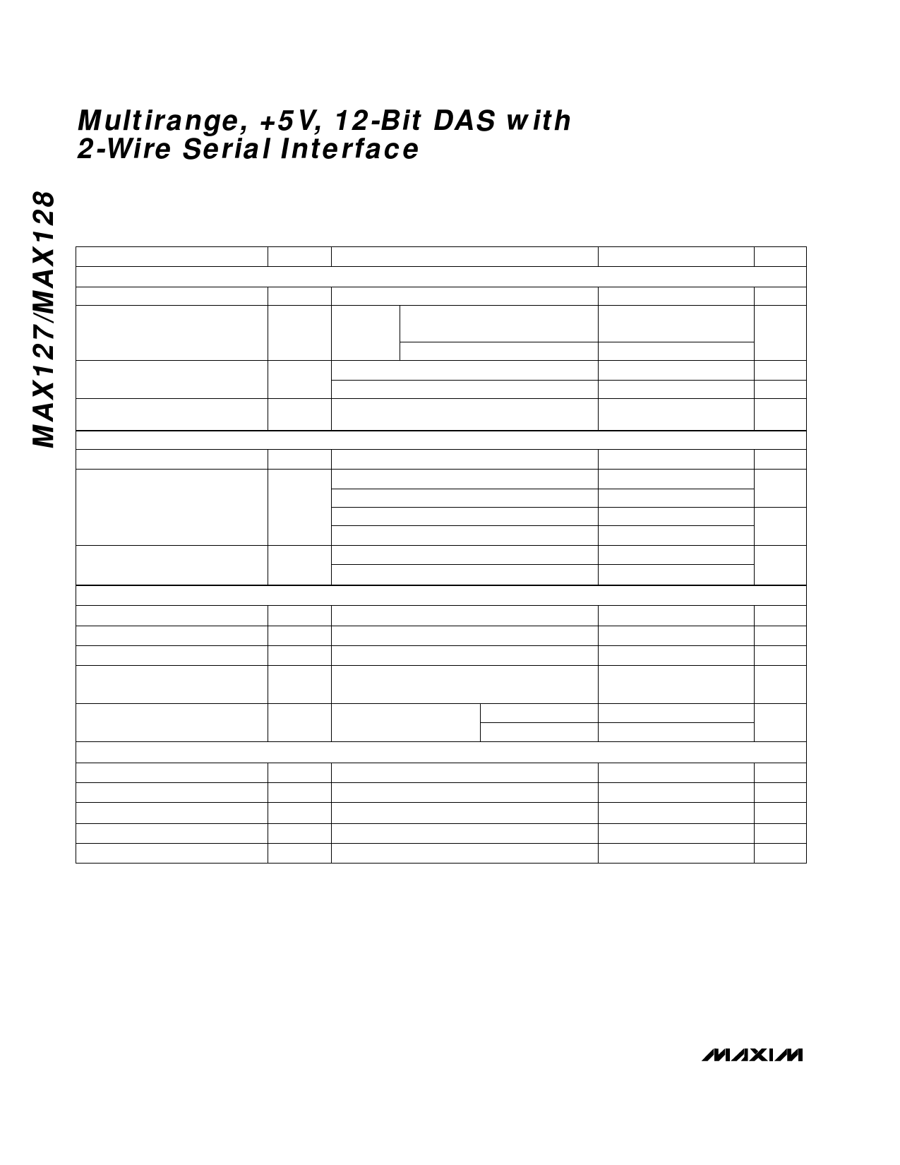
MAX127/MAX128
Multirange, +5V, 12-Bit DAS with
2-Wire Serial Interface
Electrical Characteristics (continued)
(VDD = +5V ±5%; unipolar/bipolar range; external reference mode, VREF = 4.096V; 4.7μF at REF; external clock, fCLK = 400kHz;
TA = TMIN to TMAX, unless otherwise noted. Typical values are at TA = +25°C.)
PARAMETER
SYMBOL
CONDITIONS
REFERENCE INPUT (buffer disabled, reference input applied to REF)
Input Voltage Range
Input Current
VREF = 4.18V
Normal, or STANDBY
power-down mode
FULL power-down mode
Input Resistance
Normal or STANDBY power-down mode
FULL power-down mode
REFADJ Threshold for
Buffer Disable
POWER REQUIREMENTS
Supply Voltage
VDD
Normal mode, bipolar ranges
Supply Current
Normal mode, unipolar ranges
IDD
STANDBY power-down mode (Note 6)
FULL power-down mode
Power-Supply Rejection Ratio
(Note 7)
PSRR
External reference = 4.096V
Internal reference
TIMING
External Clock Frequency Range
Conversion Time
Throughput Rate
fCLK
tCONV
Bandgap Reference
Startup Time
Power-up (Note 8)
Reference Buffer Settling Time
DIGITAL INPUTS (SHDN, A2, A1, A0)
To 0.1mV, REF bypass
capacitor fully discharged
CREF = 4.7μF
CREF = 33μF
Input High Threshold Voltage
Input Low Threshold Voltage
Input Leakage Current
Input Capacitance
Input Hysteresis
VIH
VIL
IIN
CIN
VHYS
VIN = 0V or VDD
(Note 4)
MIN TYP
2.4
10
5
VDD - 0.5
4.75
6
700
120
±0.1
±0.5
6.0
7.7
200
8
60
0.8
±0.1
0.2
MAX UNITS
4.18
V
400
μA
1
kΩ
MΩ
V
5.25
V
18
mA
10
850
µA
220
±0.5
LSB
0.4 MHz
10.0
µs
8
ksps
μs
ms
2.4
V
V
±10
µA
15
pF
V
www.maximintegrated.com
Maxim Integrated │ 4
Share Link: 