ZR36504 Просмотр технического описания (PDF) - Unspecified
Номер в каталоге
Компоненты Описание
Список матч
ZR36504 Datasheet PDF : 74 Pages
| |||
ZORAN Corporation
USBvision II Data Decoder
ZR36505 Data Sheet
31
VCLK
I Video Pixel-Clock input from camera. This input pin is 5-volt
tolerant.
32
HVALID
I Video Clock Enable input qualifier. This input pin is 5-volt
tolerant. Should be connected to GND if not used.
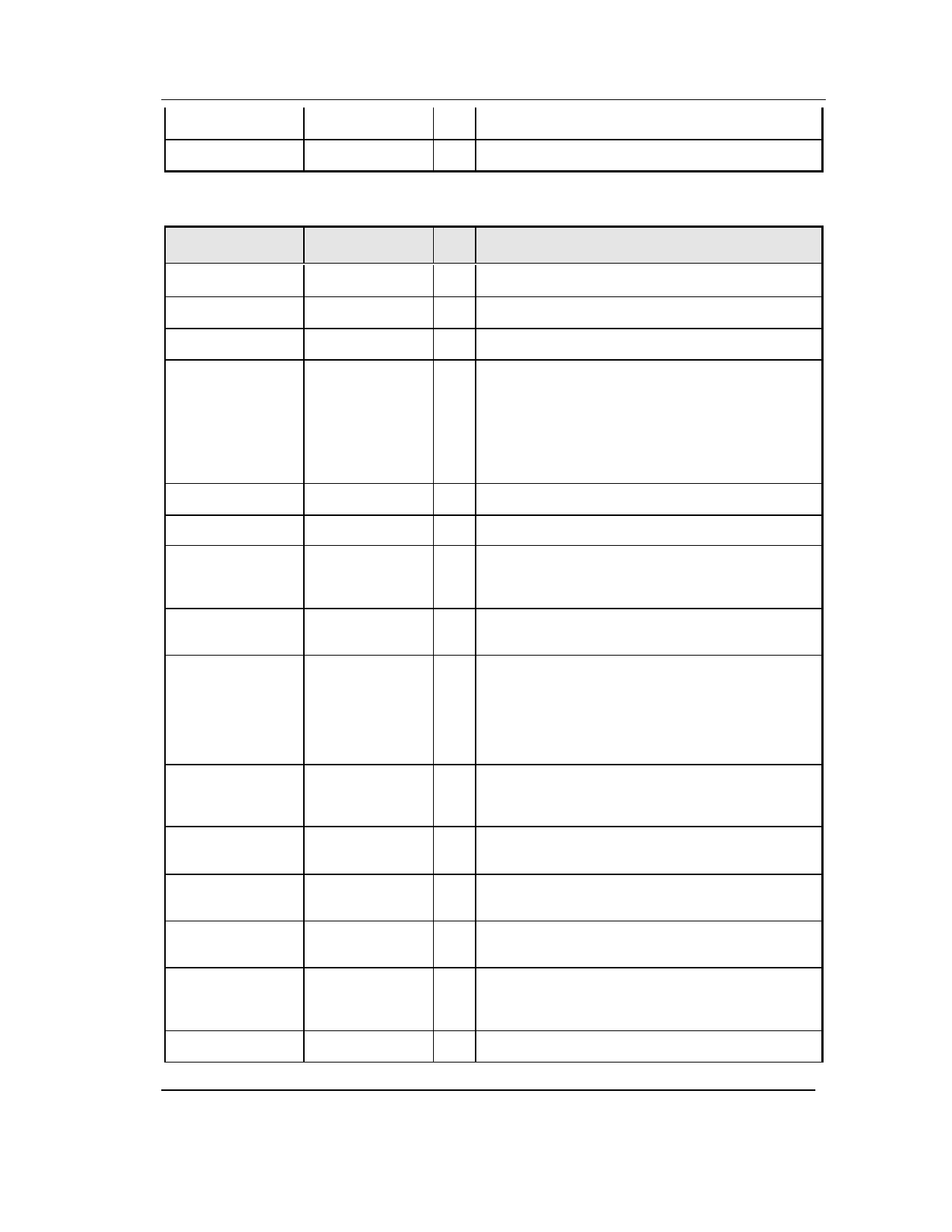
PIN DESCRIPTIONS (continued)
PIN NUMBER
SIGNAL
33
34
35
38-39
VSNC
HSNC
FID
IO-1 - IO-2
41
XIN
43
XOUT
44
BLK_FULL
45
BLK_EN
46
DAT_IN
47
FS_L
48
FS_R
49
BCLK
50
CLK48
51-52,55-64,66-
69
70
DD0-DD15
CASN
71
WRN
I/O
DESCRIPTION
I Video Vertical-Sync input signal from camera. This input pin is
5-volt tolerant. Should be connected to GND if not used.
I Video Horizontal-Sync input signal from camera. This input pin
is 5-volt tolerant. Should be connected to GND if not used.
I Video Field-ID input signal from camera. This input pin is 5 -volt
tolerant. Should be connected to GND if not used.
I/O General Programmable I/O pins. Each of these 2 pins has an
Open Drain 5v tolerant output, and it is supposed to be
connected to an external pull-up resistor. The host uses these
pins as programmable output ports by writing '0' or '1'. By writing
'1' and read back, the host can use these pins as input ports - as
this allows any external source to force the pull-up resistor.
These outputs are temporarily set to high-z while in the Suspend
position.
I Crystal Oscillator input pin (12 MHz). Crystal frequency must
have not worse than 100 PPM accuracy.
O Crystal Oscillator output pin (12 MHz).
O "Bulk-Fifo full" indication output signal. This output signal is
normally '0', and is set to '1' when the ZR36504 Bulk -Fifo is full.
This output is temporarily set to '0' while in the Suspend or
Power-Down position.
I Bulk Data Enable input. When set to '1', Bulk input data from
DAT_IN pin is sampled-in by falling edge of BCLK into the
ZR36504 Bulk -Fifo. This input pin is 5-volt tolerant.
I Data Input pin for both Audio CODEC Tx chan and Bulk Data
in. This input pin is 5 -volt tolerant, and requires an external pull-
up resistor.
O Audio Codec Frame-Sync pulse for Left channel. This signal
triggers the beginning of a new audio sample (left chan.) . This
output is temporarily set to '0' while in the Suspend or Power-
Down position.
O Audio Codec Frame-Sync pulse for Right channel. This signal
triggers the beginning of a new audio sample (right chan.) . This
output is temporarily set to '0' while in the Suspend or Power-
Down position.
O Main Clock for both Audio CODEC and Bulk Data in. This
output is temporarily set to '0' while in the Suspend or Power-
Down position.
O 48MHz Clock output for user application. This output is
temporarily set to '0' while in the Suspend or Power-Down
position.
I/O DRAM Data bus input/output pins. These pins have internal Pull-
Down resistors, and are temporarily set to High -Z while in the
Suspend or Power-Down position..
O DRAM Column-Select control signal. This output is designed to
drive 2 input pins of the external DRAM that are tied together
(LCAS+UCAS). This output is temporarily set to High -Z while
in the Suspend or Power-Down position.
O DRAM Write control signal. This output is temporarily set to
High -Z while in the Suspend or Power-Down position.
November-99
Page 10 of 10
Share Link: 