MAX1765 Просмотр технического описания (PDF) - Maxim Integrated
Номер в каталоге
Компоненты Описание
Список матч
MAX1765 Datasheet PDF : 19 Pages
| |||
800mA, Low-Noise, Step-Up DC-DC Converter
with 500mA Linear Regulator
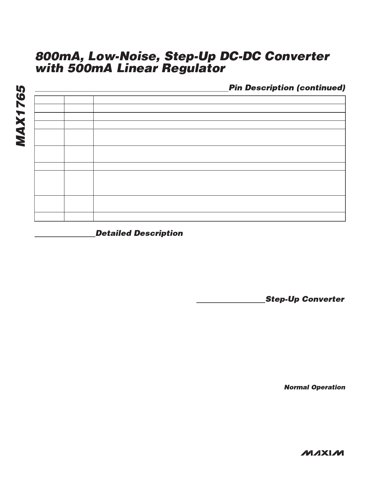
Pin Description (continued)
PIN
NAME
FUNCTION
9
ONB
ON Input. When low, the DC-DC is operational (Table 2).
10
PGND Power Ground
11
LX
Inductor connection to the drain of P-channel synchronous rectifier and N-channel switch.
12
POUT Boost Converter Power Output. POUT is the source of the P-channel synchronous-rectifier MOSFET
switch. Connect POUT to INL. Bypass POUT to PGND with a 100µF capacitor.
13
INL
Linear Regulator Power Input. Source of PFET pass device connected between INL and OUTL. Connect
INL to POUT.
14
OUTL Linear Regulator Output. OUTL can source up to 500mA. Bypass OUTL to GND with a 4.7µF capacitor.
Track-Mode Control Input for DC-DC Converter. In track mode, the boost converter output is sensed at
15
TRACK OUT and set to 0.5V above OUTL to improve efficiency. Set TRACK to OUT for track mode and to GND
for normal operation (Table 2).
16
ONL
Linear Regulator ON Input. Enables the linear regulator output when TRACK = LOW. ONA and ONB
determine the linear regulator’s output state when TRACK = HIGH.
—
EP
Exposed Pad (TSSOP Only). Internally connected to GND and PGND. Connect to a large ground plane.
Detailed Description
The MAX1765 is a highly efficient, low-noise power
supply for portable RF hand-held instruments. This
boost power supply combines an LDO linear regulator,
a low-noise, high-power, step-up switching regulator,
an N-channel power MOSFET, a P-channel synchro-
nous rectifier, shutdown control, and a precision volt-
age reference in a single 16-pin QSOP or a thermally
enhanced TSSOP-EP (Figure 1).
The switching DC-DC converter boosts a 1-cell to 3-cell
NiMH/NiCd or a single Li+ battery input to an adjustable
output voltage between 2.5V and 5.5V. The MAX1765
guarantees startup with voltages as low as 1.1V and will
remain operational down to 0.7V (Figure 2). The internal
LDO regulator provides linear postregulation for noise-
sensitive circuitry, or it can be used as a separate volt-
age output adjustable from 1.25V up to POUT.
The MAX1765 is optimized for use in cellular phones and
other applications requiring low noise during full-power
operation, as well as low quiescent current for maximum
battery life during standby and shutdown. The device
automatically transitions to a low-quiescent-current
pulse-skipping control scheme during light loads that
reduces the quiescent power consumption to 360µW.
The supply current of the device can be further reduced
to 1µA when the device is shut down. Figure 2 shows a
typical application of the MAX1765 in normal mode.
The switching regulator supports two low-noise modes:
fixed-frequency PWM for low noise in all load conditions,
and synchronization of the internal oscillator to an
external clock driving the CLK input. In TRACK mode,
the DC and linear regulator work together to maintain
excellent PSRR without excessive efficiency loss.
Additional MAX1765 features include synchronous rec-
tification for high efficiency and increased battery life,
dual boost shutdown controls for µP or a pushbutton
momentary switch, and a separate shutdown control for
the linear regulator.
Step-Up Converter
During DC-DC converter operation, the internal N-chan-
nel MOSFET turns on for the first part of each cycle,
allowing current to ramp up in the inductor and store
energy in a magnetic field. During the second part of
each cycle, the MOSFET turns off and inductor current
flows through the synchronous rectifier to the output filter
capacitor and the load. As the energy stored in the
inductor is depleted, the current ramps down and the
synchronous rectifier turns off. The CLK/SEL pin deter-
mines whether a pulse-skipping or PWM control method
is used at light loads (Table 1).
Normal Operation
Pulling CLK/SEL low selects the MAX1765’s normal
operating mode. In this mode, the device operates in
PWM when driving medium to heavy loads and auto-
matically switches to SKIP mode if the load requires
less power. SKIP mode allows higher efficiency than
PWM under light-load conditions.
10 ______________________________________________________________________________________
Share Link: 