MAX1760 Просмотр технического описания (PDF) - Maxim Integrated
Номер в каталоге
Компоненты Описание
Список матч
MAX1760 Datasheet PDF : 14 Pages
| |||
0.8A, Low-Noise, 1MHz,
Step-Up DC-DC Converter
Table 3. Component Selection Guide
PRODUCTION METHOD
INDUCTORS
TOKO type D52LC
Surface mount
TOKO type D518LC
Sumida CDRH5D18
Sumida CDRH4D28
CAPACITORS
AVX TPS series
Kemet T510 series
Sanyo POSCAP series
—
DIODES
EIC SB series
Motorola MBR0520L
—
—
Table 4. Component Suppliers
SUPPLIER
PHONE
AVX
EIC
Kemet
USA: 843-448-9411
USA: 916-941-0712
USA: 810-287-2536
Motorola
USA: 408-629-4789
Japan: 81-45-474-7030
Sumida
USA: 847-956-0666
Japan: 011-81-3-3667-3302
TOKO
USA: 847-297-0070
Note: Please indicate that you are using the MAX1760 when
contacting these component suppliers.
time constant is:
tSS = RSSCSS
where RSS ≥ 470kΩ.
Placing a capacitor across the lower resistor of the cur-
rent-limiting resistive divider provides both current-limit
and soft-start features simultaneously (Figures 4 and 5).
Inductor Selection
The MAX1760’s high switching frequency allows the
use of a small 3.3µH surface-mount inductor. The cho-
sen inductor should generally have a saturation current
rating exceeding the N-channel switch current limit;
however, it is acceptable to bias the inductor current
into saturation by as much as 20% if a slight reduction
in efficiency is acceptable. Lower current-rated induc-
tors may be used if ISET is employed to reduce the
peak inductor current (see the Setting the Switch
Current Limit and Soft-Start section). For high efficien-
cy, choose an inductor with a high-frequency ferrite
core material to reduce core losses. To minimize radiat-
ed noise, use a toroid or shielded inductor. See Table 3
for suggested components and Table 4 for a list of
component suppliers. Connect the inductor from the
battery to the LX pin as close to the IC as possible.
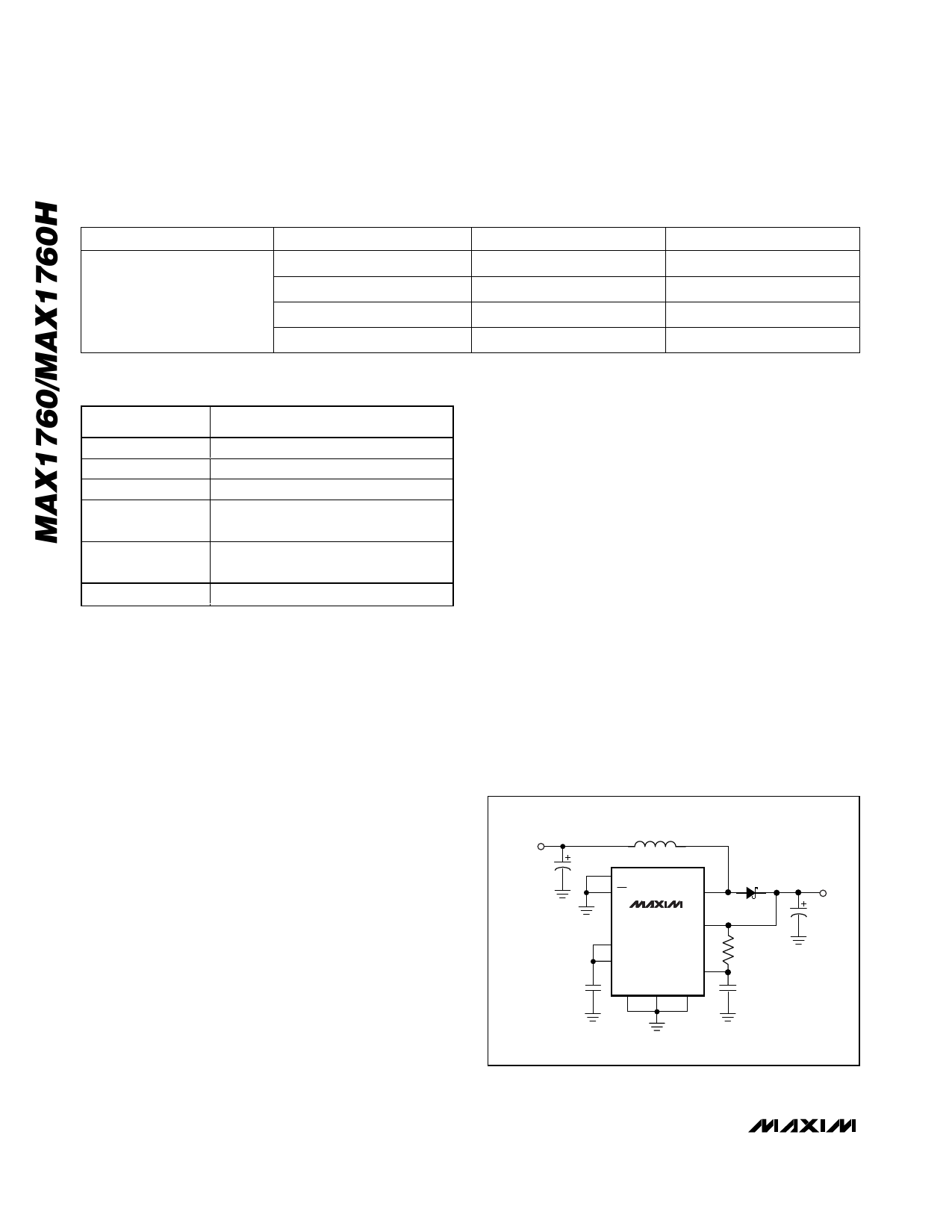
External Diode
For output voltages greater than 4V, an external
Schottky diode must be connected from LX to POUT, in
parallel with the on-chip synchronous rectifier (Figure
6). The diode should be rated for 0.5A. Representative
devices are Motorola MBR0520L, Nihon EP05Q03L, or
generic 1N5817. This external diode is also recom-
mended for applications that must start with input volt-
ages at or below 1.8V. The Schottky diode carries
current during startup and after the synchronous rectifi-
er turns off; thus, its current rating only needs to be
500mA. Connect the diode as close to the IC as possi-
ble. Do not use ordinary rectifier diodes; their slow
switching speeds and long reverse-recovery times ren-
der them unacceptable. For circuits that do not require
startup with inputs below 1.8V and have an output of 4V
or less, no external diode is needed.
Input and Output Filter Capacitors
Choose input and output filter capacitors that will ser-
vice the input and output peak currents with accept-
able voltage ripple. Choose input capacitors with
working voltage ratings over the maximum input volt-
VIN = 0.7V
TO VOUT
3.3µH
33µF
0.22µF
CLK/SEL
ON
LX
MAX1760
POUT
ISET
REF
OUT
PGND GND FB
MRB0520L
4.7Ω
0.68µF
VOUT
100µF
Figure 6. Connection with External Schottky Diode for Output
Voltages Greater than 4V, or to Assist Low-Voltage Startup
10 ______________________________________________________________________________________
Share Link: 