L38812 Просмотр технического описания (PDF) - Unisonic Technologies
Номер в каталоге
Компоненты Описание
Список матч
L38812 Datasheet PDF : 8 Pages
| |||
UTC L388 12 LINEAR INTEGRATED CIRCUIT
PIN DESCRIPTIONS
16-pin
SO
1
2
3
4
5
6
7
8
9
10
11
12
13
14
15
16
18-pin
DIP
16
17
18
1
2
3
4
5
6
7
8
9
10
11
12
13
14
15
SYMBOL
CTR
-Txin
+Txin
F2out
Txout
TxDetin
TxDetout
NDet
CMP
RxDetout
RxDetin
Rxout
F5out
+Rxin
-Rxin
V+
GND
NC
DESCRIPTION
Control input for gain dynamics (25 or 50dB), mute and disable.
Transmitter channel negative input. Input impedance 3kΩ.
Transmitter channel positive input. Input impedance 100kΩ.
Output of the second amplifier in the transmitter channel.
Transmitter channel output. Min. ac load impedance 10kΩ.
Input of the transmitter channel signal detector. Input impedance 13kΩ.
Output of the transmitter channel signal detector. Goes negative referred
to the internal ref. voltage of app.2V when a transmitter signal is present.
Background noise detector output. Goes positive referred to the internal
ref. Voltage of app.2V when a background noise signal is present.
Comparator input..
Summing point to the different Detector outputs.
Output of the receiver channel signal detector. Goes positive referred to
the internal ref. Voltage of app.2V when a receiver signal is present
Input of the receiver channel signal detector. Input impedance 13kΩ.
Receiver channel output. Min. ac load impedance 10kΩ.
Output of the second amplifier in the receiver channel.
Receiver channel positive input. Input impedance 140kΩ.
Receiver channel negative input,Input impedance 20kΩ.
Supply of the speech switching circuitry. A shunt regulator, voltage
apprx. 3.3V at 1.0mA.
System ground.
Not connected.
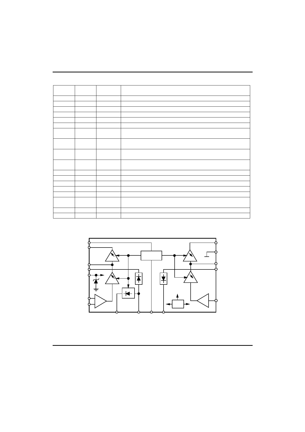
BLOCK DIAGRAM(16-pin SO package)
1
5
F3
4
6
15
+
F2
Control
12
16
F6
13
11
F5
2-
3
F1
+
8
Ref.
7
9 10
F4+ 14
UTC UNISONIC TECHNOLOGIES CO. LTD 2
QW-R108-013,A
Share Link: 