CDB6420 Просмотр технического описания (PDF) - Cirrus Logic
Номер в каталоге
Компоненты Описание
Список матч
CDB6420 Datasheet PDF : 52 Pages
| |||
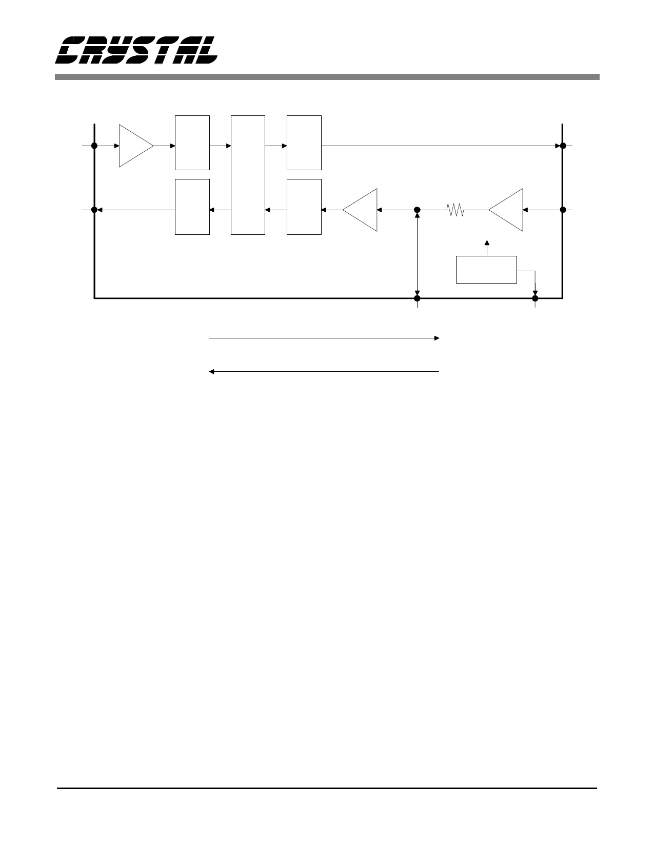
CS6420
NI
PGA
17
ADC
DAC
0,6,9.5,12 dB
D
S
P
NO
DAC
ADC
PGA
4
0,6,9.5,12 dB
AO
3
API
34 dB
1kΩ
20
2.12V
18 APO
BANDGAP
3.5V
19 MB
FAR-END
Receive Path
Transmit Path
Figure 4. Analog Interface
NEAR-END
and they are post-compensated internally to pre-
vent any resultant passband droop. The ADCs also
expect a maximum of 1 Vrms (2.8 Vpp) at their in-
puts (which are biased around 2.12 VDC). A signal
of higher amplitude will clip the ADC input and
may result in poor echo canceller performance. See
the Design Considerations section for more details.
The outputs are delta-sigma digital to analog con-
verters (DACs) and have similar requirements to
the ADCs. The DACs are pre-compensated to ex-
pect a single-pole RC filter with a corner frequency
at 4 kHz. The full scale voltage output from a DAC
is 1 Vrms (2.8 Vpp) swinging around a DC bias of
2.12 V.
Acoustic Interface
The pins API (pin 20), APO (pin 18), MB (pin 19),
and AO (pin 3) make up the Acoustic Interface. A
block diagram of the Acoustic Interface is shown in
Figure 4.
API and APO are, respectively, the input and out-
put of the built-in analog pre-amplifier. The pre-
amplifier is an inverting amplifier with a fixed gain
of 34 dB biased around an input offset voltage
(Voff) of 2.12 V. APO is the output of the pre-am-
plifier after a 1 kΩ resistor. The circuitry connected
to the amplifier input must present low source im-
pedance (<100Ω) to the API pin or the gain will be
reduced. When using the pre-amplifier, connecting
a 0.022 µF capacitor to ground off APO will pro-
vide the anti-aliasing filter required by the ADC, as
shown in Figure 2. The pre-amplifier may be by-
passed by clearing Mic (Register 0, bit 15) using the
Microcontroller Interface (see Microcontroller In-
terface section), grounding API through a capacitor,
and driving APO directly. In this case, the signal into
APO must be low-pass filtered by a single-pole RC
filter with a corner frequency at 8 kHz (see Figure 3).
Following the pre-amplifier is a programmable an-
alog gain stage (PGA) which is controllable
through the Microcontroller Interface. This gain
DS205PP2
9
Share Link: 