KCUSB16 Просмотр технического описания (PDF) - KAWASAKI MICROELECTRONICS
Номер в каталоге
Компоненты Описание
Список матч
KCUSB16 Datasheet PDF : 4 Pages
| |||
OVERVIEW
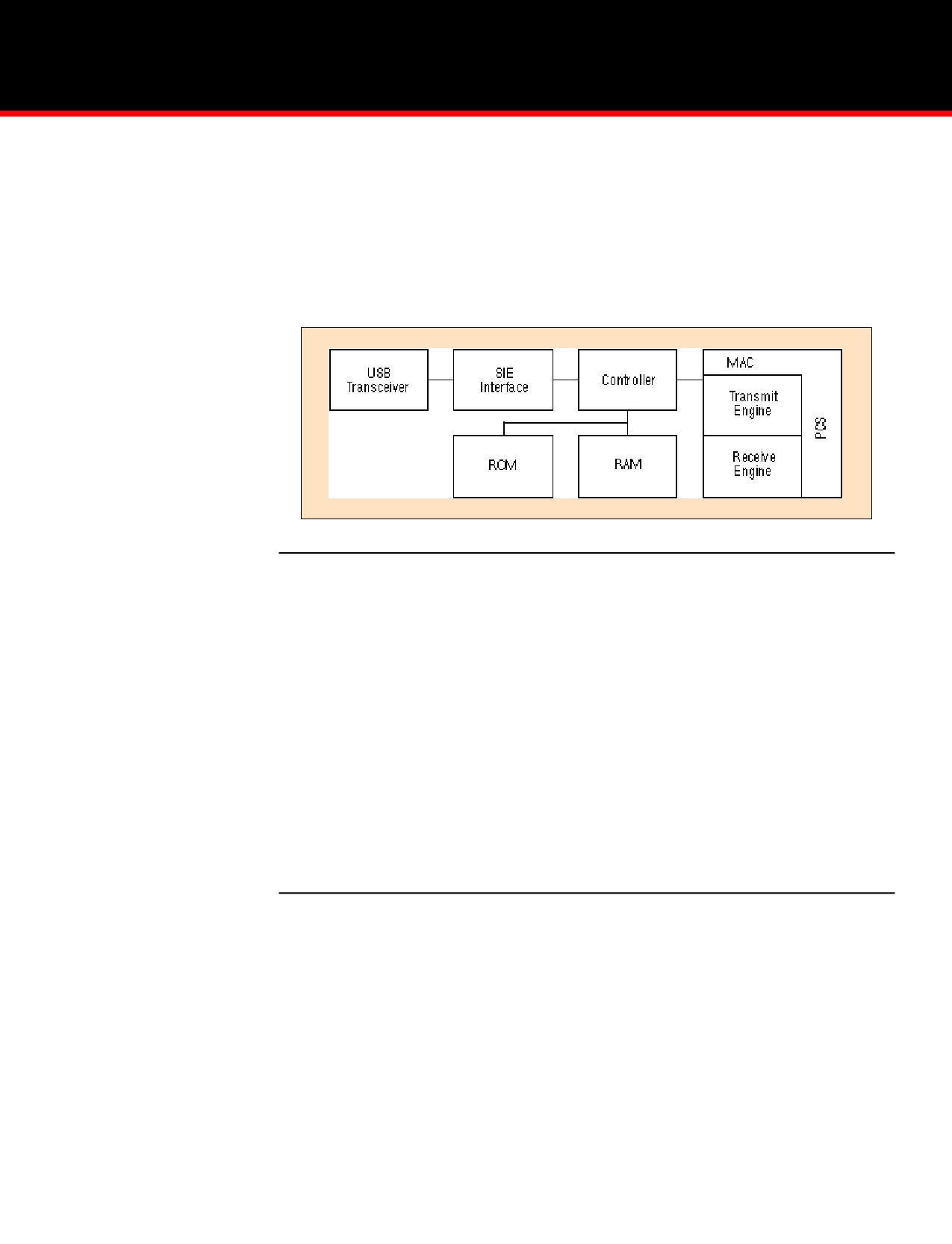
The KCUSB16 Controller has been specifically designed to provide
an easy to use interface between a USB and Ethernet 802.3. The
chip contains a USB transceiver and SIE (Serial Interface Engine),
a micro-controller with internal RAM and ROM, a 10Mhz Ethernet
MAC and all the necessary function blocks needed to control and
integrate the above functions. To simplify system design, we have
added several key functions such as an I2C interface for serial EPROMS
as well as a memory controller that can interface to external SRAM,
DRAM and ROM, should additional memory be required beyond what
is on-chip. The block diagram of figure 1 highlights the primary functions
of the KCUSB16.
Block Diagram of Ethernet Controller
KEY FEATURES
• High Speed Microprocessor
• Supports DMA Transfers
• 3KB RAM
• 8KB ROM
• Minimal external components required
• Glue-less interface to PHY and memory
Interface Options
• Serial EPROM interface
• External SRAM, DRAM and ROM
USB Functionality
• 12 M bits/second transfer rate
• Guaranteed service latency
• Guaranteed bandwidth allocation
• Built-in error detection and recovery
Ethernet Functionality
• Full Duplex operation
• Conforms to 802.3 specification
Software
• Standard Win 95 “Class” drivers
• NDIS drivers provided
Physical Specifications
• 3.3V, 0.5 Micron CMOS Technology
• Low power
• 100 pin QFP Package
SIE
(SERIAL INTERFACE ENGINE)
The USB Function SIE interface specification describes the interfacing
signals between the USB Function SIE Reference VHDL design
(referred to as ‘Function SIE’) and the surrounding USB Function
interface logic. The Function SIE utilizes a Slave oriented eight bit bus
interface. Interface signals are divided into four groups:
• Status: provides output information regarding the results
of the last attempted USB transaction.
• Bus Interface: interface signals to access data to/from
the SIE
• Transceiver Interface: interface signals to connect the SIE
to a USB compatible differential transceiver
• Control: Function input to the SIE to control the state
transitions of the SIE state machine based on the following
variables:
• Valid Address/Endpoint values
• Availability of Buffer space or Data
• Error conditions
For the remainder of this document the ‘Host’ will refer to the
hardware/software to which the SIE is connected in the Function. The
USB Host will be referred to as “USB Host”.
Share Link: 