DTS-1600A Просмотр технического описания (PDF) - Directed Energy, Inc. An IXYS Company
Номер в каталоге
Компоненты Описание
Список матч
DTS-1600A Datasheet PDF : 4 Pages
| |||
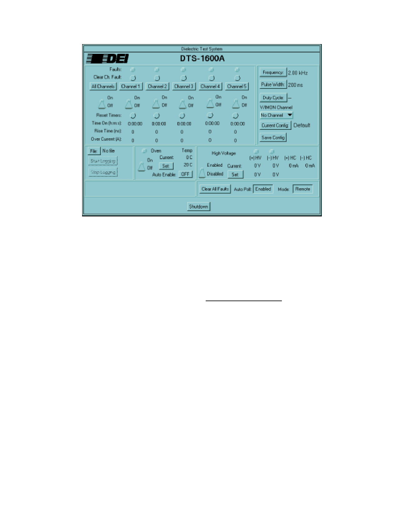
Figure 4
GUI Main Control Panel
tween the system and the user. Designed with
the research and manufacturing environments in
mind, the GUI allows the user to configure and
monitor all samples under test. Created with Na-
tional Instruments LabWindows under Windows
95, the control screens appear like the front panel
of a test instrument. Using a mouse and key-
board, the software is intuitive and easy to learn,
requiring very little time and energy to become
proficient in the control of the DTS-1600A.
The GUI provides control over the following pa-
rameters:
• Output Voltage from 0 to ±1600V
• Pulse Width from 1µs to 4.75ms
• Pulse Frequency from 200Hz to 20KHz
• Oven temperature from ambient to 180°C
• Enable/disable testing of each sample
• Pulse rate-of-rise time for each sample
• Current trip setpoint for each sample
• File logging of all test data
Test data are logged in a standard ASCII text file.
From this file, the user can retrieve data corre-
sponding to the start of each sample test, failures
of individual samples, as well as periodic test pa-
rameter updates. The log file can be imported into
and analyzed using a spreadsheet program such
as Microsoft Excel or Lotus 1-2-3.
The main GUI control screen is shown in Figure 4
above.
The DTS-1600A is a fully integrated test system,
ready for use. The control software is designed to
enable immediate use of the system, without ad-
ditional programming on the part of the user.
SYSTEM OVERVIEW
The DTS-1600A system consists of three basic
modules. The first module is the Pentium proces-
sor-based control computer and General Purpose
Interface Bus (GPIB). The computer and GUI op-
erate as the master control unit, and allow the
user to interface with the system. Using software
created in the National Instruments LabWindows/
CVI environment with custom defined functions,
the user has complete control of the system from
this location. The control computer interfaces to
the slave control unit over a GPIB bus.
The rack-mounted slave control unit and high
voltage section is the second module. It consists
of a GPIB interface, a microcontroller and pulse
generator, five ±1600V pulser modules, oven
control circuitry, front panel interface, and high
voltage and support power supplies. The internal
microcontroller is responsible for decoding the
software commands from the control computer
and implementing them in hardware. It communi-
cates with all peripheral cards via an internal RS-
485 interface.
Share Link: 