LT3574IMS Просмотр технического описания (PDF) - Linear Technology
Номер в каталоге
Компоненты Описание
Список матч
LT3574IMS Datasheet PDF : 24 Pages
| |||
LT3574
Applications Information
Table 2. Common Resistor Values for 2:1 Transformers
VOUT (V)
NPS
RFB (kΩ) RREF (kΩ) RTC (kΩ)
3.3
2.00
37.4
6.04
18.7
5
2.00
56
6.04
28
12
2.00
130
6.04
66.5
15
2.00
162
6.04
80.6
Table 3. Common Resistor Values for 3:1 Transformers
VOUT (V)
NPS
RFB (kΩ) RREF (kΩ) RTC (kΩ)
3.3
3.00
56.2
6.04
20
5
3.00
80.6
6.04
28.7
10
3.00
165
6.04
54.9
Table 4. Common Resistor Values for 4:1 Transformers
VOUT (V)
NPS
RFB (kΩ) RREF (kΩ) RTC (kΩ)
3.3
4.00
76.8
6.04
19.1
5
4.00
113
6.04
28
Output Power
A flyback converter has a complicated relationship be-
tween the input and output current compared to a buck
or a boost. A boost has a relatively constant maximum
input current regardless of input voltage and a buck has a
relatively constant maximum output current regardless of
input voltage. This is due to the continuous nonswitching
behavior of the two currents. A flyback converter has both
discontinuous input and output currents which makes it
similar to a nonisolated buck-boost. The duty cycle will
affect the input and output currents, making it hard to
predict output power. In addition, the winding ratio can
be changed to multiply the output current at the expense
of a higher switch voltage.
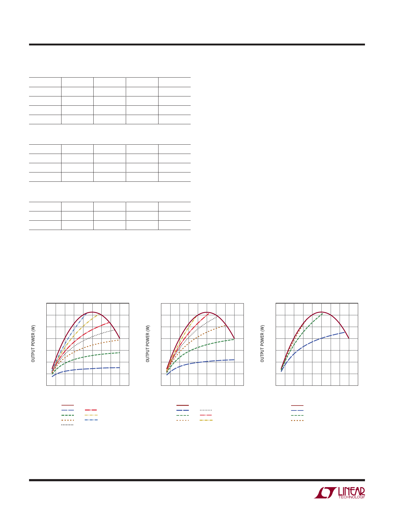
The graphs in Figures 1-3 show the maximum output
power possible for the output voltages 3.3V, 5V and 12V.
The maximum power output curve is the calculated output
power if the switch voltage is 50V during the off-time. To
achieve this power level at a given input, a winding ratio
value must be calculated to stress the switch to 50V,
resulting in some odd ratio values. The curves below are
examples of common winding ratio values and the amount
of output power at given input voltages.
One design example would be a 5V output converter with
a minimum input voltage of 20V and a maximum input
voltage of 30V. A three-to-one winding ratio fits this design
example perfectly and outputs close to 2.5W at 30V but
lowers to 2W at 20V.
3.5
3.0
2.5
2.0
1.5
1.0
0.5
0
0 5 10 15 20 25 30 35 40 45
INPUT VOLTAGE (V)
3574 F01
MAX POWER OUTPUT
1:1
5:1
2:1
7:1
3:1
10:1
4:1
Figure 1. Output Power for 3.3V Output
3.5
3.0
2.5
2.0
1.5
1.0
0.5
0
0 5 10 15 20 25 30 35 40 45
INPUT VOLTAGE (V)
3574 F02
MAX POWER OUTPUT
1:1
4:1
2:1
5:1
3:1
7:1
Figure 2. Output Power for 5V Output
3.5
3.0
2.5
2.0
1.5
1.0
0.5
0
0 5 10 15 20 25 30 35 40 45
INPUT VOLTAGE (V)
3574 F03
MAX POWER OUTPUT
1:1
2:1
3:1
Figure 3. Output Power for 12V Output
3574f
10
Share Link: 