L78LR05 Просмотр технического описания (PDF) - SANYO -> Panasonic
Номер в каталоге
Компоненты Описание
Список матч
L78LR05 Datasheet PDF : 6 Pages
| |||
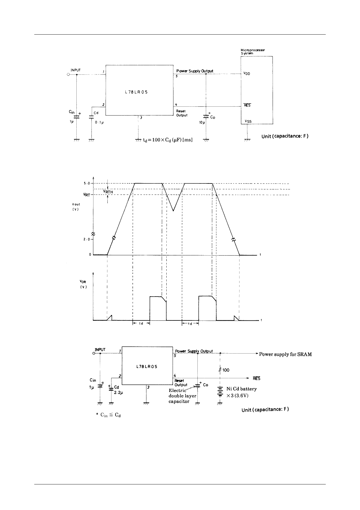
Sample Application Circuit 1
L78LR05
Note 1 : When the capacitance of Cd is large, the capacitor may not discharge completely, causing td to be made shorter than a set value. If this is a
problem, either connect a high speed diode (DS442) between pin2 (anode side) and pin5 (cathode side) or ensure an adequate discharge time by
using values for capacitors Cin and Cd such that Cin>Cd.
Note 2 : If a pull-up resistor is connected to the reset output pin externally, it is possible to cause a sink current up to 4mA to flow.
Reset Operation
Sample Application Circuit 2 (Direct battery backup)
Since the leakage current at the output pin (pin5) of the L78LR05 is so low as 2μA or less, a backup circuit can be
implemented by connectiong an electric double layer capacitor (super capacitor : NEC, gold capacitor : Matsushita Elec-
tric) or a Ni Cd battery direct to the output pin. Since a reverse blocking diode, which has been so far connected to the
output pin, is not required, a regulated power-supply voltage can be supplied to a load during the steady-state operation,
without voltage drop caused by the diode and effects of temperature characteristics, current characteristics of the diode. No
battery-regulator switching circuit is required at the battery backup start mode.
Note 3 : The capacitance of reset output signal delay capacitor Cd must exceed that of input capacitor Cin. If the capacitance of Cd is small, a reset pulse
signal may be generated once when the main power source is turned off (at the battery backup start mode).
No.2622–3/6
Share Link: 