PBL38814 Просмотр технического описания (PDF) - Ericsson
Номер в каталоге
Компоненты Описание
Список матч
PBL38814 Datasheet PDF : 14 Pages
| |||
PBL 388 14
Loudspeaker amplifier
The loudspeaker amplifier drives
directly a 25 - 50Ω impedance loudspeaker.
The single ended loudspeaker amplifier
has an internal gain regulation that prevents
distortion in case of insufficient supply
voltage. The loudspeaker volume control
can be solved in two different ways. One is
to use a conventional potentiometer that
will act as an ac voltage divider at the power
amplifier input pin 23. The second is to
control the gain of the power amplifier by
dc. at pin 21. See fig.16. The controlling
element can be a potentiometer or a digital
control from a µ-processor. See figure 17.
Input
Vin 1 µF
23 LSPin
PBL 388 14
GND
17
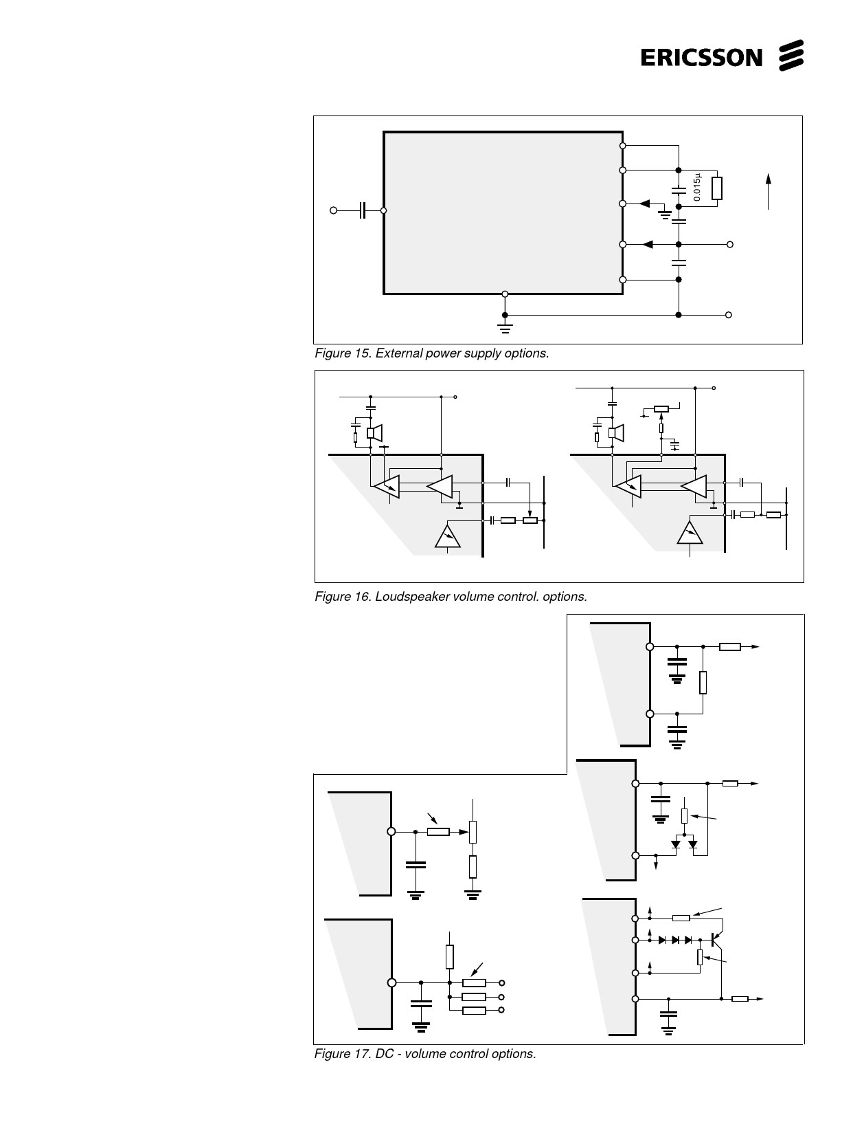
Figure 15. External power supply options.
LL 20
LSP 19
VOL 21
VA 22
GNDA 18
0.015 µ used only
with inductive load
I VOL
50Ω
Load
V out
100 µF
I+L + 16 V
+ VA
+
-
Some optional features using
the dc. set volume control on
the loudspeaker amplifier of
PBL 388 14. ( Fig. 17. )
+ supply
+
50 Ω LOUD
SPEAKER
0V
19 21
22
+
+
0V
50 Ω LOUD
SPEAKER
0V
19
21
22
+ supply
The DC set volume control has an
wholly internal function to lower the gain at
low supply voltages. This is to avoid that
23
17
PBL 388 14
12
23
0V
17
PBL 388 14
12
the power stage dies and causes breaks in
F6
the output signal at low supply currents in
AC-control
F6
0V
DC-control
combination with high input signals. This
DC controlled volume is externally
accessible in the PBL 388 14 and can thus Figure 16. Loudspeaker volume control. options.
be utilized in several ways.
a). To control the loudspeaker volume supply voltage and will at all times give the
with a DC- voltage from a potentiometer. optimum distortion limiting performance.
b). To control the loudspeaker volume
with a digital signal ( for ex. 8 - levels ).
c). An AGC can be combined with the
volume control by connecting a resistor
from the DC - control pin 21 to the output of
the receiver detector at pin 10. Care has to
be taken not to disturb the speech switching
balance. If the resistor is made too low
ohmic the same value has to be applied on
the transmitter detector output at pin 6 as
well as that the capacitors at the detector
outputs have to be made bigger.
d). A ”softclipping” with a fixed level
can be combined with the volume control.
A draw back with the fixed level is that when
setting it in to inhibit clipping distortion at
low supply voltage, the level will not increase
even if the supply voltage would allow it.
e). A ”softclipping” that is controlled by
the ”real” output level that means that the
"softclipping" will follow the changes in the
PBL
388 14 21
This resistor sets
+
the max. attenuation
a).
This resistor sets
the min. attenuation
position on the pot.
PBL
388 14
+
Weighted
resistors
21
b).
Three bit
digital
signal
Figure 17. DC - volume control options.
21
PBL
388 14
10
c).
To volume
control
Resistor that is added
and which determines
the dynamics of the AGC
21
+ + pin 4
PBL
10µF
388 14
To volum
control
Resistor that sets the
"softclipping" level
12
d).
19
PBL 22
388 14
18
21
e).
Sets the steepness
of the "softclipping"
+
10µF
Resistor that sets the
"softclipping" level
To volume
control
10
Share Link: 