VP301 Просмотр технического описания (PDF) - SANYO -> Panasonic
Номер в каталоге
Компоненты Описание
Список матч
VP301 Datasheet PDF : 6 Pages
| |||
VP301
Surge Protection
Surge protection is required when this device is connected to a CRT. This product requires the same protection as earlier
products.
A. Termination spark gap
B. Surge suppression resistor
C. Surge suppression diode (Installed in the vicinity of the IC output pin.)
Caution: The value of surge suppression resistors must be determined taking both the stipulated discharge test and the
required frequency bandwidth into account.
Notes on Mounting
• Heat sink mounting
Since the specified heat sink is required to operate a mounted video pack, we recommend the following mounting
technique. (See the thermal design item for details on the required heat sink.) In particular, since the package used for
this product is even more compact than that used in the earlier VPA series, the following points require special care.
(These are recommendations.)
1. A tightening torque of between 39 and 58 N·cm is recommended. Note that 49 N·cm is the standard torque.
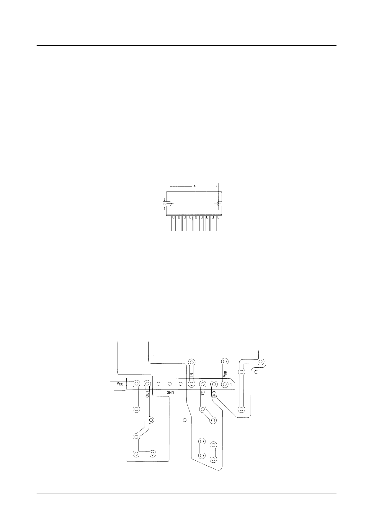
2. The bolt hole spacing in the heat sink should match that of the IC. In particular, the bolt hole spacing should be made
as close as possible, within the range that mounting is possible, to the dimensions A and B in the package
dimensions drawing, as shown below.
3. Use either the truss screws (truss bolts) or binding screws (binding bolts) stipulated in the JIS standards as the
mounting bolts. Also, use washers to protect the IC case.
4. Foreign matter, such as machining chips, must not be left trapped between the IC case and the heat sink. If grease is
applied to the junction surface, be sure to apply the grease evenly.
5. Solder the IC leads to the printed circuit board after mounting the heat sink to the IC.
Note: The heat sink is absolutely required to operate this video pack. Never, in any situation, apply power to a video pack
as an independent device. The video pack may be destroyed.
• Peripheral wiring and ground leading
• Inputs and outputs must be laid out as direct lines and must not cross.
• If a double-sided printed circuit board is used, the output pattern must not be laid out on the other side of the printed
circuit board from the ground pattern, since this would increase the output capacitance.
IC Peripheral Pin Layout (Top view)
No. 5429-4/6
Share Link: 