HMC223MS8 Просмотр технического описания (PDF) - Hittite Microwave
Номер в каталоге
Компоненты Описание
Список матч
HMC223MS8 Datasheet PDF : 4 Pages
| |||
v01.0300
MICROWAVE CORPORATION
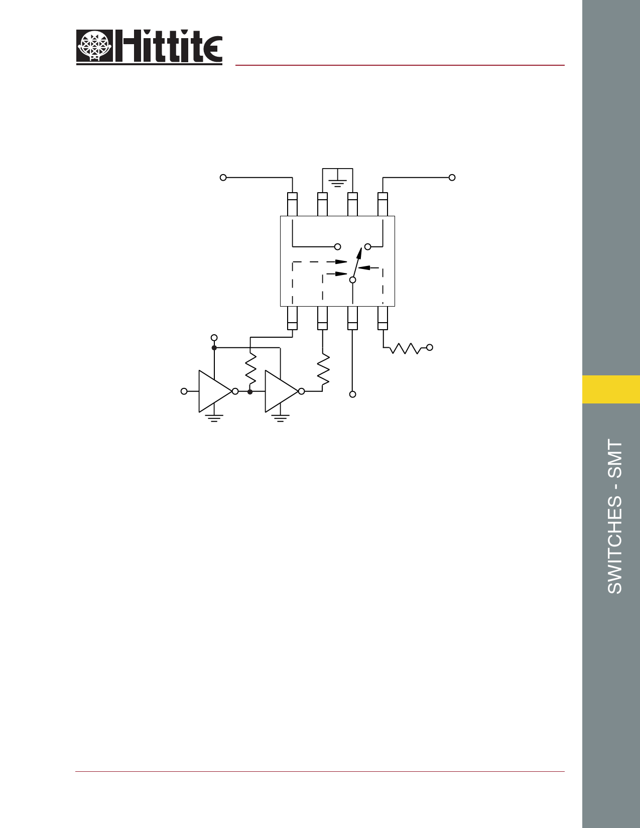
Typical Application Circuit
RF2
HMC223MS8
GaAs MMIC T/R SWITCH
4.5 - 6.0 GHz
RF1
GND GND
+V
A
B
R1
R2
Vdd
+V
R3
CTL
CMOS
CMOS
7
RF
Notes:
1. Control Inputs A and B can be driven directly with CMOS logic (HC) with V of 3 to 8 Volts applied to the CMOS logic
gates and to pin 4 of the RF switch.
2. Set V to 5 Volts and use HCT series logic to provide a TTL driver interface.
3. Highest RF signal power capability is achieved with V set to +10V. However, the switch will operate properly (but at lower
RF power capability) at bias voltages down to +3V.
4. RF ByPass: Do not use RF bypass capacitors on Vdd, A or B ports. Resistors R1, R2, R3 = 100 Ohms should be
placed close to the Vdd, A and B ports. Use resistor size 0402 to minimize parasitic inductances and capacitances.
5. DC Blocking capacitors are not required for each RF port.
6. Evaluation PCB available.
See Section 8 for Layout Guidelines Application Note.
For price, delivery, and to place orders, please contact Hittite Microwave Corporation:
12 Elizabeth Drive, Chelmsford, MA 01824 Phone: 978-250-3343 Fax: 978-250-3373
Visit us at www.hittite.com, or Email at sales@hittite.com
7 - 97
Share Link: 