CS5460 Просмотр технического описания (PDF) - Cirrus Logic
Номер в каталоге
Компоненты Описание
Список матч
CS5460 Datasheet PDF : 34 Pages
| |||
CS5460
2. GENERAL DESCRIPTION
The CS5460 is a CMOS monolithic power mea-
surement device with an energy computation en-
gine. The CS5460 combines a programmable gain
amplifier, two ∆Σ modulators, two high rate filters,
system calibration, and power calculation func-
tions to compute Energy, VRMS, IRMS, and Instan-
taneous Power.
The CS5460 is designed for power meter applica-
tions and is optimized to interface to shunts or cur-
rent transformers to measure current, and a
resistive divider or transformer to measure voltage.
To accommodate various input voltage levels due
to shunts, the current channel includes a program-
mable gain amplifier (PGA) which allows the user
to measure either 150mVRMS or 30mVRMS signals.
The CS5460 includes two high-rate digital filters
which output data at a (MCLK/K)/1024 output word
rate (OWR). A high-pass filter in both channels can
be enabled to remove the DC content from the input
signal before the energy calculations are made.
To ease communication between the CS5460 and a
micro-controller, the converter includes a simple
three-wire serial interface which is SPI™ and Mi-
crowire™ compatible. The serial port also contains
a Schmitt Trigger input on its serial clock (SCLK)
to allow for slow rise time signals.
2.1 Theory of Operation
The CS5460 is designed to operate from a single
+5 V supply or dual ±2.5 V supplies, to provide a
30mVRMS or 150mVRMS range for the current
channel and to provide a 150mVRMS range for the
voltage channel. With single supply, the CS5460 is
designed to accommodate common mode signals
of -0.25V to VA+.
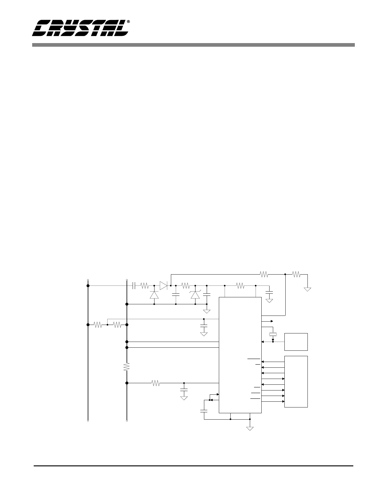
Figure 3 illustrates the CS5460 connected to a ser-
vice to measure power in a single-phase 2-wire sys-
tem while operating in a single supply
configuration. Figure 4 illustrates the CS5460 con-
figured to measure power in a single-phase 3-wire
system.
N
L
500 Ω
470 nF
R2
R1
500 Ω
100 µF
10 kΩ
5 kΩ
10 Ω
0.1 µF
14
VA+
3
VD+
0.1 µF
9
CPV *
VIN+
CS5460
PFMON 17
CPUCLK 2
XOUT 1
2.5 MHz to
20 MHz
10 VIN-
15 IIN-
XIN 24
Optional
Clock
Source
To Service
RS
RPI *
CPI *
0.1 µF
16 IIN+
12 VREFIN
11 VREFOUT
RESET 19
CS 7
SDI 23
SDO 6
SCLK 5
INT 20
EDIR 22
EOUT 21
VA-
13
DGND
4
* Refer to Input Current Protection
Serial
Data
Interface
Figure 3. Typical Connection Diagram (One-Phase 2-Wire)
DS279PP5
9
Share Link: 