M3004LD Просмотр технического описания (PDF) - STMicroelectronics
Номер в каталоге
Компоненты Описание
Список матч
M3004LD Datasheet PDF : 10 Pages
| |||
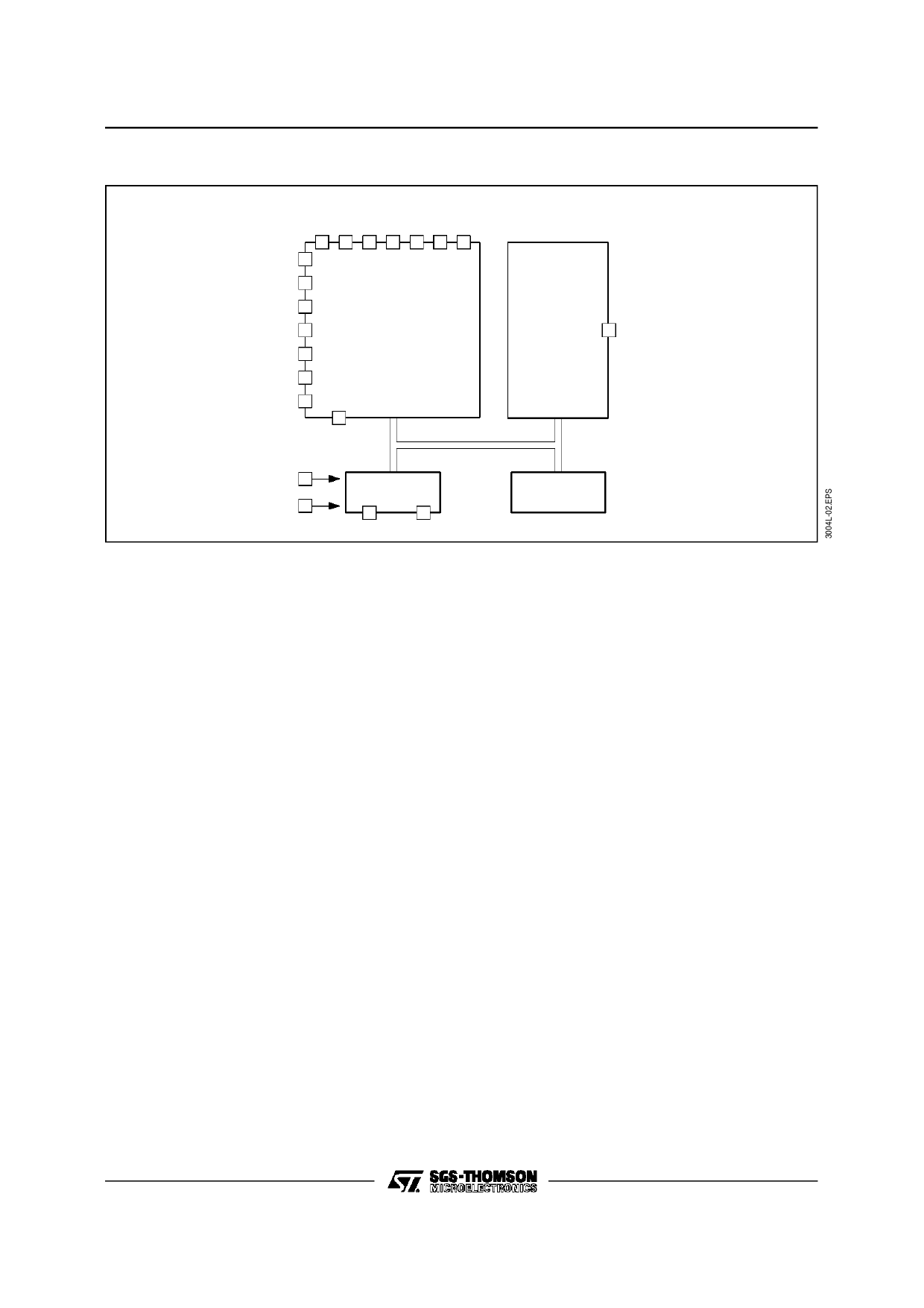
M3004LAB1 - M3004LD
BLOCK DIAGRAM
DRV OUTPUTS
0N 1N 2N 3N 4N 5N 6N
0N
S 1N
E
N 2N
I
N
3N
P
U
4N
T
S
5N
6N
KEYBOARD
SCAN
ADRM
PULSE
DISTANCE
MODULATOR
REMO
OUTPUT
VDD
OSCILLATOR
VSS
OSCI OSCO
CONTROL
LOGIC
INPUTS AND OUTPUTS
Key matrix inputs and outputs (DRV0N to
DRV6N and SEN0N to SEN6N)
The transmitter keyboard is arranged as a scanned
matrix. The matrix consists of 7 driver outputs and
7 sense inputs as shown in Figure 1. The driver
outputs DRV0N to DRV6N are open drain N-chan-
nel tran-sistors and they are conductive in the
stand-by mode. The 7 sense inputs (SEN0N to
SEN6N) enable the generation of 56 command
codes. With 2 external diodes all 64 commands are
addressable. The sense inputs have P-channel
pull-up transistors so that they are HIGH until they
are pulled LOW by connecting them to an output
via a key depression to initiate a code transmission.
ADDRESS MODE INPUT (ADRM)
The sub-system address and the transmission
mode are defined by connecting the ADRM input
to one or more driver outputs (DRV0N to DRV6N)
of the key matrix. If more than one driver is con-
nected to ADRM, they must be decoupled by di-
odes. This allows the definition of seven
sub-system addresses as shown in table 3. If driver
DRV6N is connected to ADRM, the data output
format of REMO is modulated or if not connected,
flashed.
The ADRM input has switched pull-up and pull-
down loads. In the stand-by mode only the pull-
down device is active. Whether ADRM is open
(sub-system address 0, flashed mode) or con-
nected to the driver outputs, this input is LOW and
will not cause unwanted dissipation. When the
transmitter becomes active by pressing a key, the
pull-down device is switched off and the pull-up
device is switched on, so that the applied driver
signals are sensed for the decoding of the sub-sys-
tem address and the mode of transmission.
The arrangement of the sub-system address cod-
ing is such that only the driver DRVnM with the
highest number (n) defines the sub-system ad-
dress, e.g. if drivers DRV2N and DRV4N are con-
nected to ADRM, only DRV4N will define the
sub-system address. This option can be used in
systems requiring more than one sub-system ad-
dress. The transmitter may be hard-wired for sub-
system address 2 by connectingDRV1N to ADRM.
If now DRV3N is added to ADRM by a key or a
switch, the transmitted sub-system address
changes to 4. A change of the sub-system address
will not start a transmission.
2/10
Share Link: 