MSM7620 Просмотр технического описания (PDF) - Oki Electric Industry
Номер в каталоге
Компоненты Описание
Список матч
MSM7620 Datasheet PDF : 28 Pages
| |||
¡ Semiconductor
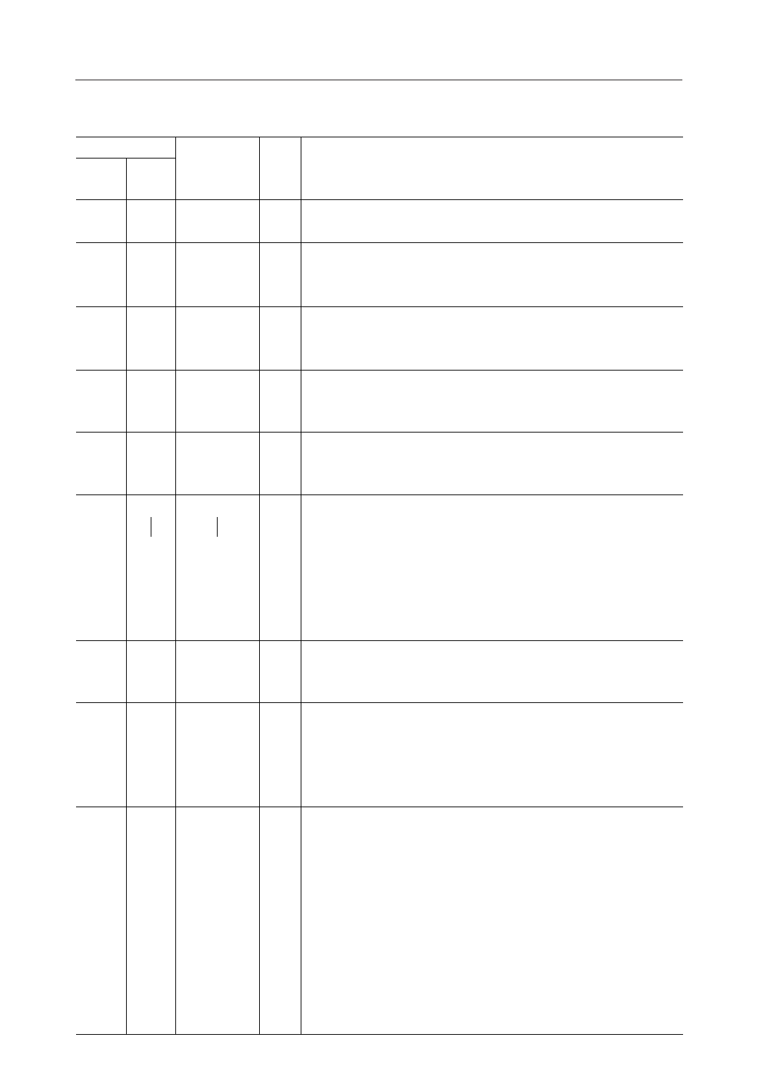
MSM7620
(3/5)
Pin
32-pin 64-pin
SSOP QFP
10
11
11
12
12
13
13
14
14
15
—
19
—
30
—
33
—
34
—
51
—
52
20
35
21
36
23
38
Symbol
RIN
SCK
SYNC
SOUT
ROUT
PD0
PD11
PD12
PD13
PD14
PD15
X1/CLKIN
X2
PWDWN
Type
Description
I Receive serial data.
Input the m-law PCM signal synchronized to SYNC and SCK. Data is read in at the fall of SCK.
I Clock pin for transmit/receive serial data. This pin uses the external
SCK or the SCKO.
Input the PCM CODEC transmit/receive clock (64 to 2048 kHz).
I Sync signal for transmit/receive serial data. This pin uses the external
SYNC or SYNCO.
Input the PCM CODEC transmit/receive sync signal (8 kHz).
O Transmit serial data.
This pin outputs the m-law PCM signal synchronized to SYNC and SCK.
This pin is in a high impedance state while there is no data output.
O Receive serial data.
This pin outputs the m-law PCM signal synchronized to SYNC and SCK.
This pin is in a high impedance state while there is no data output.
I/O Bidirectional bus for parallel data transfer between the Master Chip and
Slave Chip when used in a cascade connection.
The PD15 pin corresponds to MSB.
This pin is in a high impedance state while there is no data output. Data
is loaded in at the falling edge of SFx.
I External input for the basic clock or for the crystal oscillator.
Input the basic clock (18 MHz).
Refer to the internal clock generator circuit example.
O Crystal oscilator.
Used to configure the oscillation circuit.
Refer to the internal clock generator circuit example.
When inputting the basic clock externally, insert a 5 pF capacitor with
excellent high frequency characteristics between X2 and GND.
I Power-down mode control.
"L": Power-down mode
"H": Normal operation mode
During power-down, all input pins are disabled and output pins are in
the following sates :
High impedance : SOUT, ROUT, PD0 to 15
"L": SYNCO, SCKO
"H": OF1, OF2
Holds the last state : WDT, IRLD
Not affected: X2, MCKO
Reset after power-down is released.
7/28
Share Link: 