ML7012 Просмотр технического описания (PDF) - Oki Electric Industry
Номер в каталоге
Компоненты Описание
Список матч
ML7012 Datasheet PDF : 22 Pages
| |||
1Semiconductor
FEDL 7012-04-01
ML7012-04
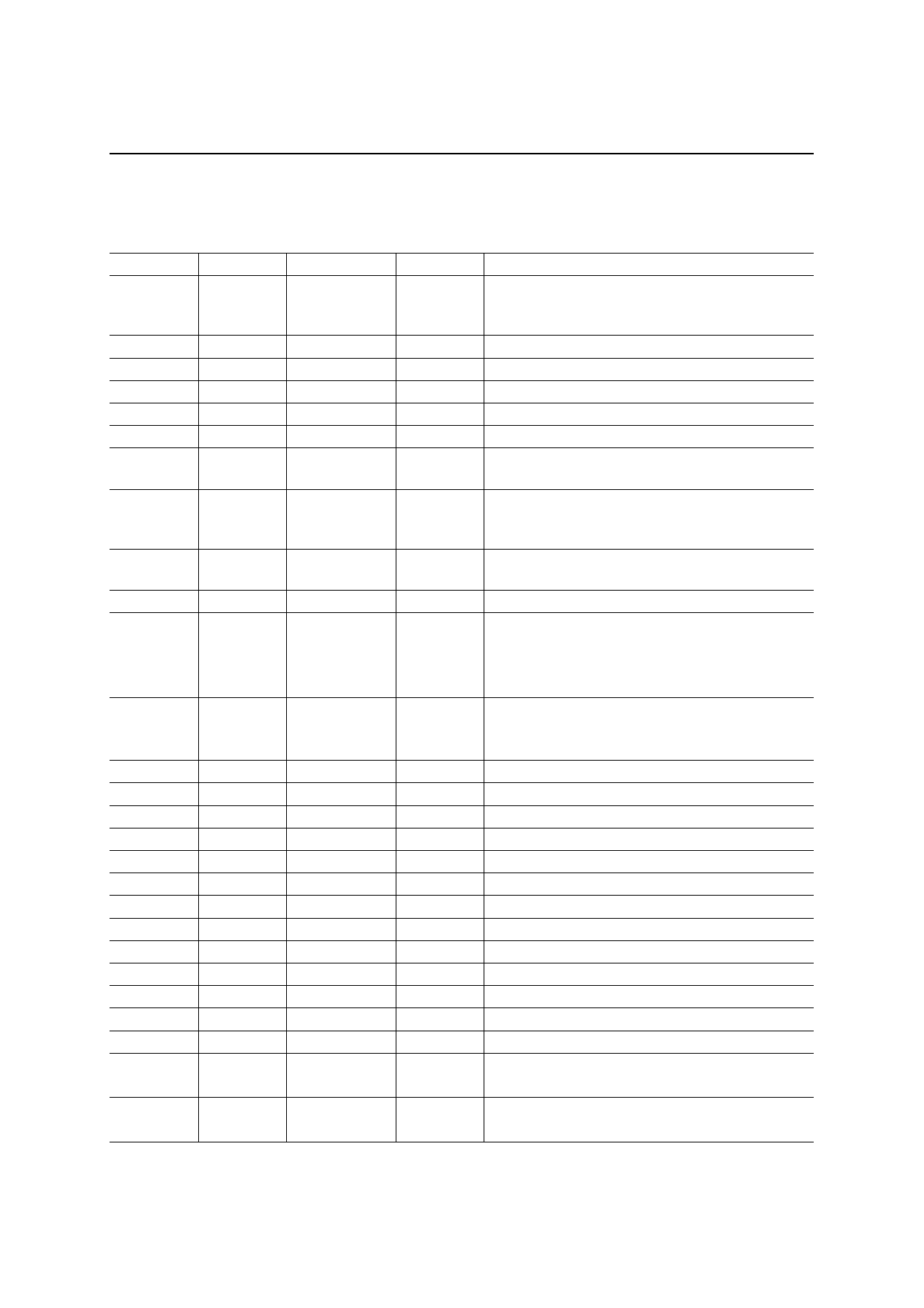
S Register List
Refer to the “Bit map S register list” if the function is specified as “Bit map register”.
Register No. Set Range
Unit
Initial Value
Function
0
0-255
time
Setting of the number to receive the ring signal at
0
automatic receive mode. When set to “0”, automatic
receive function is disabled.
1
0-255
time
0
The number of receiving rings
2
—
—
—
Not used
3
0-127
ASCII code
13
Carriage return code
4
0-127
ASCII code
10
Line feed code
5
0-127
ASCII code
8
Back space code
6
4-255
sec
Pause time from off-hook to start dialing (Only when
4
setting ATX0, X1, and X3)
7
1-115
sec
Waiting time for carrier from the far end modem. It is
60
set to on-hook when no carrier is detected after the
time specified.
8
0-255
sec
Pause time for dialing. It is referred when dial
2
character < , > is used.
9
—
—
—
Not used
Carrier lost detection time
10
1-255
1/10 sec
14
It is set to on-hook automatically when the lost of
carrier signal is longer than the specified time.
Carrier lost detection is invalid when 255 is set.
DTMF tone transmit time
11
1-255
1/100 sec
9
Sets DTMF transmit time. DTMF tone is continuously
transmitted when set at 255.
12
—
—
—
Not used
13
—
—
—
Not used
14
—
—
170 Bit map register
15
—
—
—
Not used
16
—
—
0
Bit map register
17
—
—
—
Not used
18
0-255
sec
0
Timer for loop back test
19
—
—
—
Not used
20
—
—
—
Not used
21
—
—
18
Bit map register
22
—
—
244 Bit map register
23
—
—
23
Bit map register
24 to 27
—
—
—
Not used
34*
0-255
dB
Sets the level attenuator of transmit carrier.
2
When 15 to 255 is input, value is fixed to 15.
35*
0-255
dB
Sets the sending level attenuator of DTMF signal.
0
When 15 to 255 is input, value is fixed to 15.
*Refer to the “Analog Interface Characteristics” for the analog transmit level for S34 and S35.
16/22
Share Link: 