M54HC4075D Просмотр технического описания (PDF) - STMicroelectronics
Номер в каталоге
Компоненты Описание
Список матч
M54HC4075D Datasheet PDF : 9 Pages
| |||
M54HC4075
Table 6: AC Electrical Characteristics (CL = 50 pF, Input tr = tf = 6ns)
Test Condition
Symbol
Parameter
VCC
(V)
tTLH tTHL Output Transition
2.0
Time
4.5
6.0
tPLH tPHL Propagation Delay 2.0
Time
4.5
6.0
Table 7: Capacitive Characteristics
Value
TA = 25°C
-40 to 85°C -55 to 125°C Unit
Min. Typ. Max. Min. Max. Min. Max.
30 75
8 15
7 13
40 80
10 16
9 14
95
110
19
22 ns
16
19
100
120
20
24 ns
17
20
Test Condition
Value
Symbol
Parameter
VCC
(V)
CIN Input Capacitance 5.0
CPD Power Dissipation
Capacitance (note 5.0
1)
TA = 25°C
-40 to 85°C -55 to 125°C Unit
Min. Typ. Max. Min. Max. Min. Max.
5 10
10
10 pF
24
pF
1) CPD is defined as the value of the IC’s internal equivalent capacitance which is calculated from the operating current consumption without
load. (Refer to Test Circuit). Average operating current can be obtained by the following equation. ICC(opr) = CPD x VCC x fIN + ICC/3 (per gate)
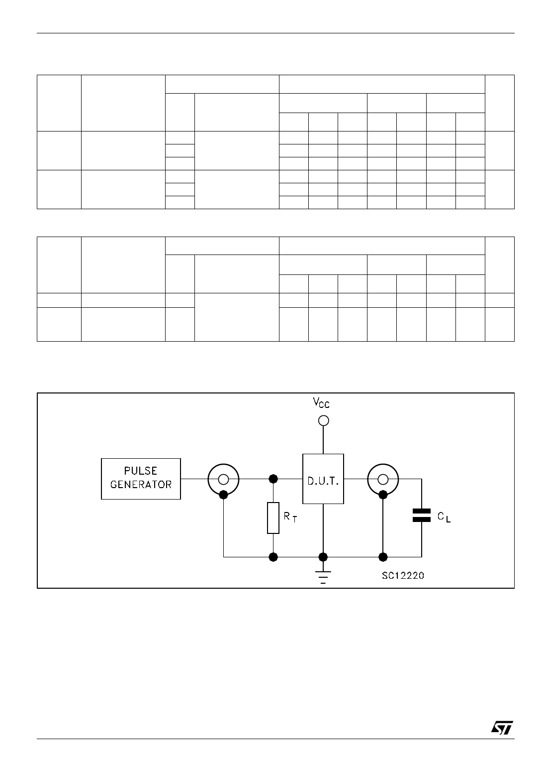
Figure 3: Test Circuit
CL = 50pF or equivalent (includes jig and probe capacitance)
RT = ZOUT of pulse generator (typically 50Ω)
4/9
Share Link: 