DS2114 Просмотр технического описания (PDF) - Dallas Semiconductor -> Maxim Integrated
Номер в каталоге
Компоненты Описание
Список матч
DS2114 Datasheet PDF : 6 Pages
| |||
DS2114
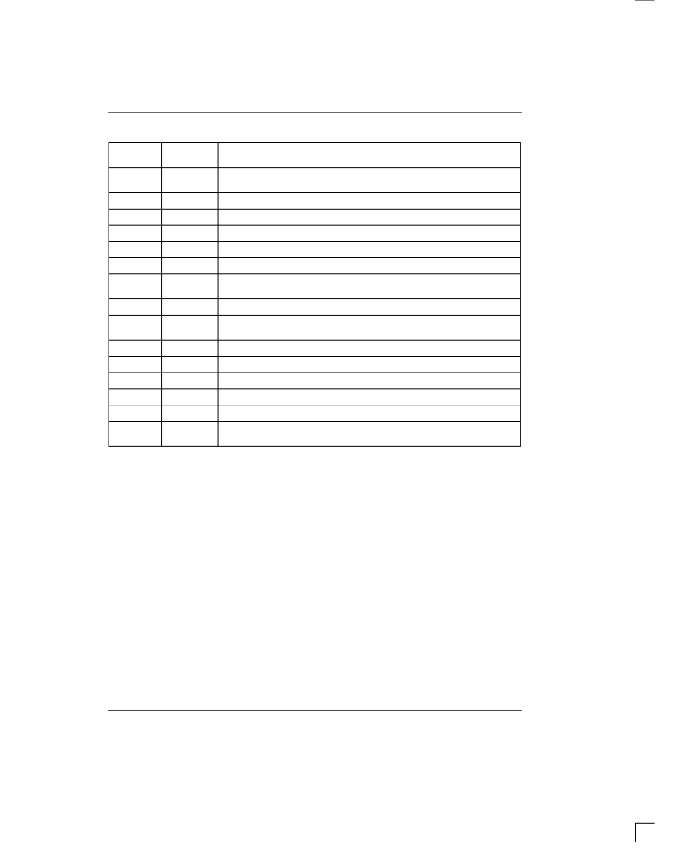
PIN DESCRIPTION Table 1
DS2114Z
PIN
SYMBOL
DESCRIPTION
1
TERMPWR1 Termination Power 1. Should be connected to the SCSI TERMPWR line. Must
be decoupled with either a 2.2 µF or 4.7 µF. See Figure 2.
2
R1
Signal Termination 1. 110 ohms termination.
3
R2
Signal Termination 2. 110 ohms termination.
4
R3
Signal Termination 3. 110 ohms termination.
5
R4
Signal Termination 4. 110 ohms termination.
6
R5
Signal Termination 5. 110 ohms termination.
7
VREF1 Reference Voltage 1. Must be externally connected directly to the VREF2 pin.
Must be decoupled with a 4.7 µF capacitor as shown in Figure 2.
8
GND
Ground. Signal ground; 0.0 volts.
9
TERMPWR2 Termination Power 2. Should be connected to the SCSI TERMPWR line. Must
be decoupled with either a 2.2 µF or 4.7 µF. See Figure 2.
11
R6
Signal Termination 6. 110 ohms termination.
12
R7
Signal Termination 7. 110 ohms termination.
13
R8
Signal Termination 8. 110 ohms termination.
14
R9
Signal Termination 9. 110 ohms termination.
10, 16
NC
No Connect. Do not connect any signal to these pins.
15
VREF2 Reference Voltage 2. Must be externally connected directly to the VREF1 pin.
Must be decoupled with a 4.7 µF capacitor as shown in Figure 2.
070198 4/6
Share Link: 